Imaging is a form of art. Much of our fellowship is dedicated to learning the art of angiography. Just like surgeries can be meticulous, careful, and detail-oriented masterpieces — or ugly hacks — so can angiograms. In my experience, there is a lot more emphasis placed in residencies on teaching artful surgery than in fellowships on artful angiography. An ugly angiogram is not just bad looks — it is of lesser diagnostic value and negatively impacts the operator’s reputation, especially when presented in meetings. This section is an art class in angiography
Positioning
The head should be straight. Absent anatomical deformity or other medical considerations, there is no reason why the head should be at angle with detector. There are many ways to safely and comfortably achieve this in most circumstances
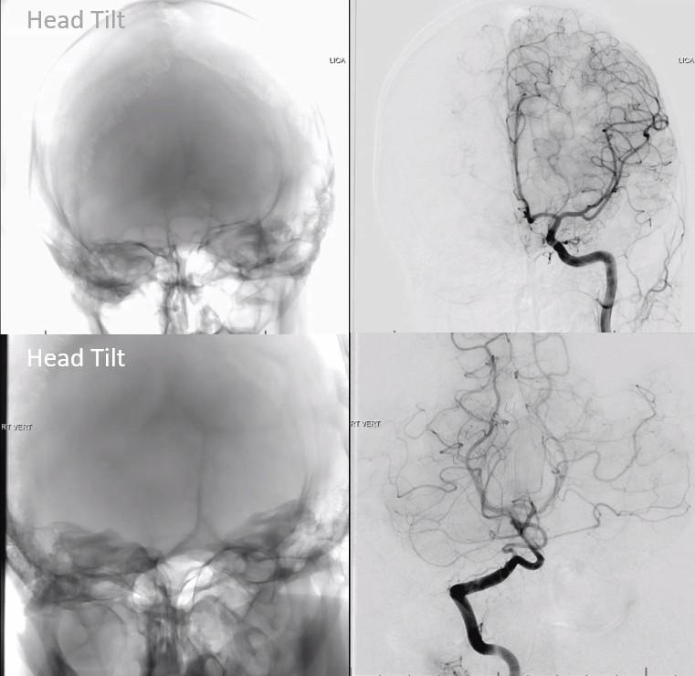
Here is what not to do:
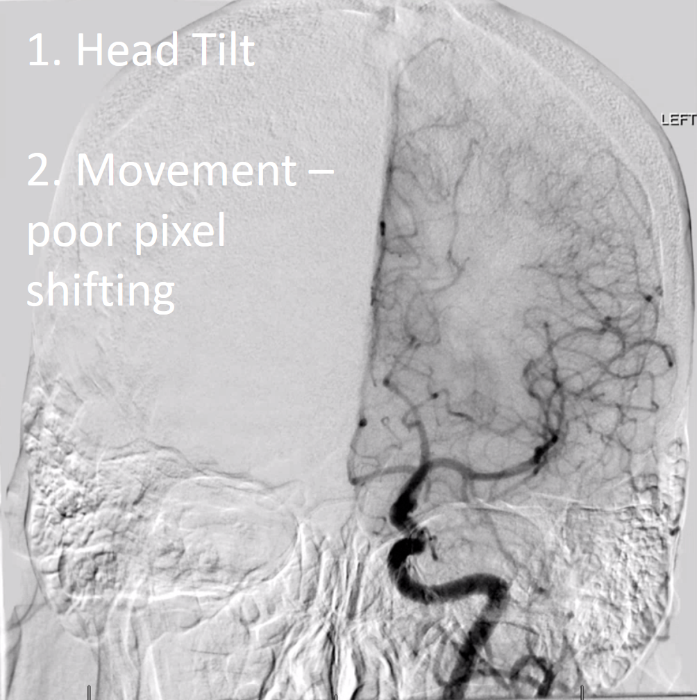
Here, a combination of tilt and suboptimal pixelshiting produce a rather wanting image
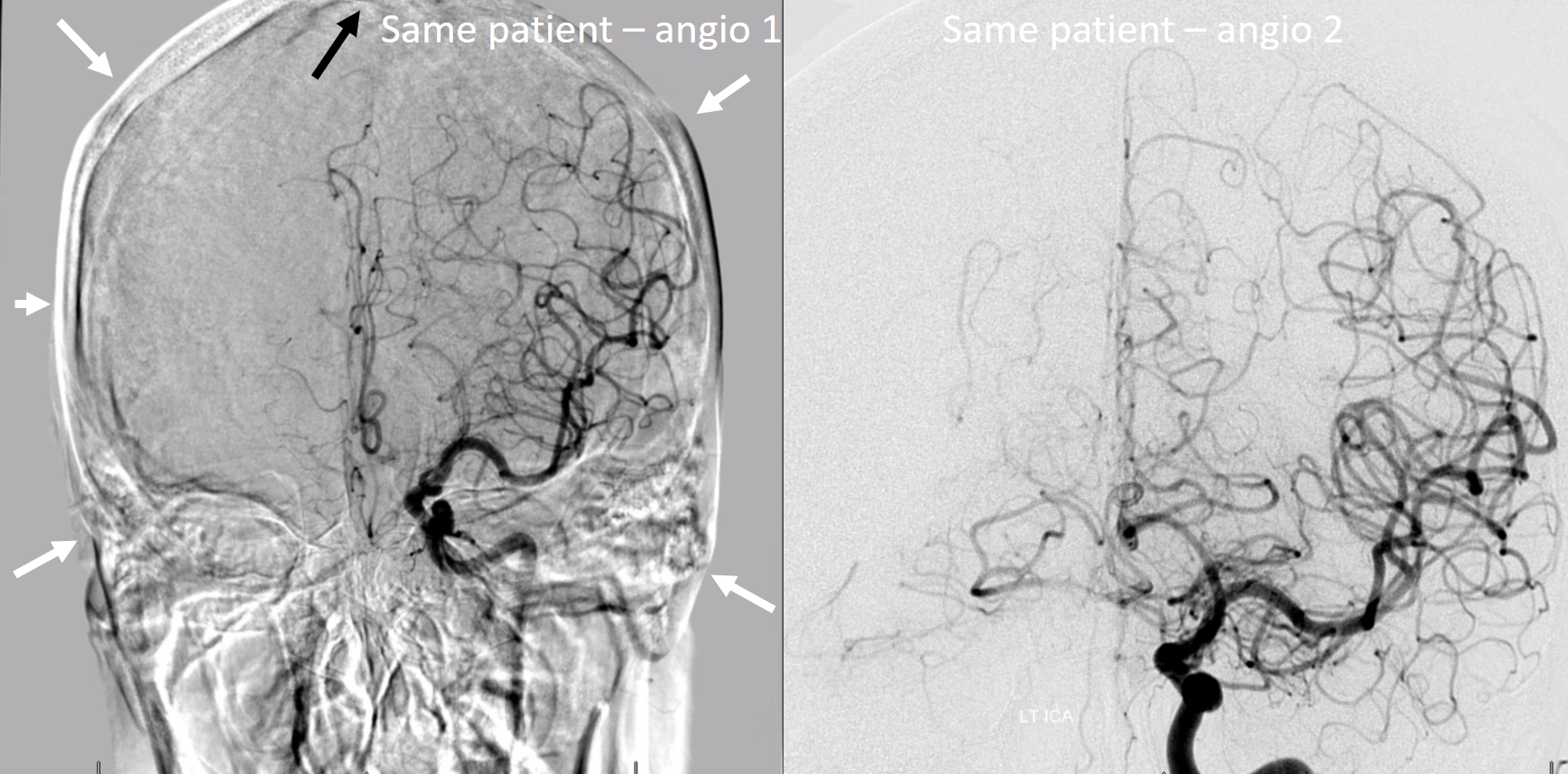
Images below are of the same patient. Look at the difference… its not just positioning — more on other stuff below
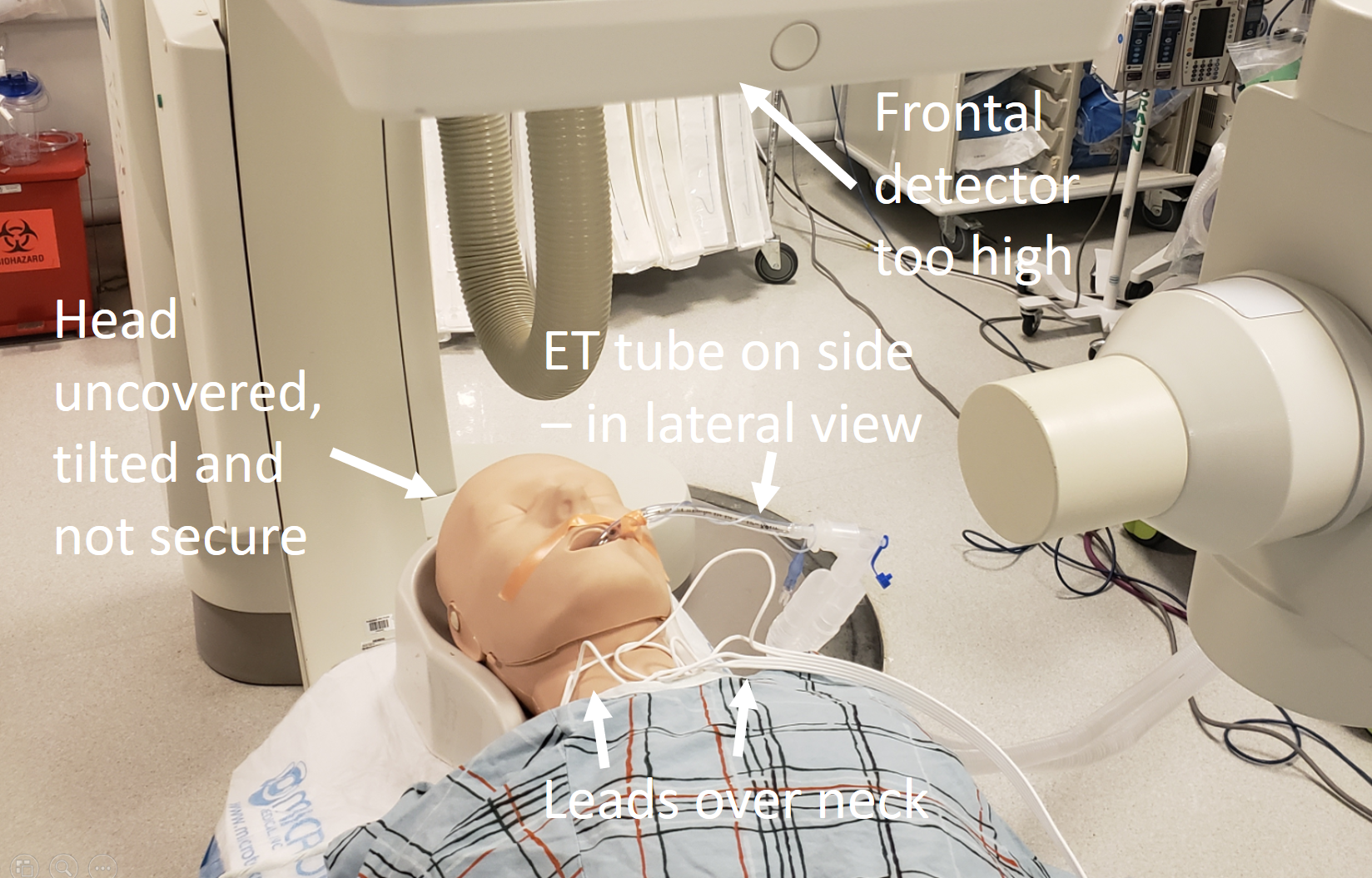
Tubes, wires, gown buttons…
There is no reason to have these over the head — with rare exception of intraprocedural monitoring / EEG leads. ET tubes can be secured to the chest — not hanging off the side with all kinds of moving tubing attached to them. ECG leads do not have to hang over the neck — they can be easily positioned along the lateral chest wall. Gown buttons dont have to compete with cervical arteries. Having these in the field is not dangerous — just sloppy.
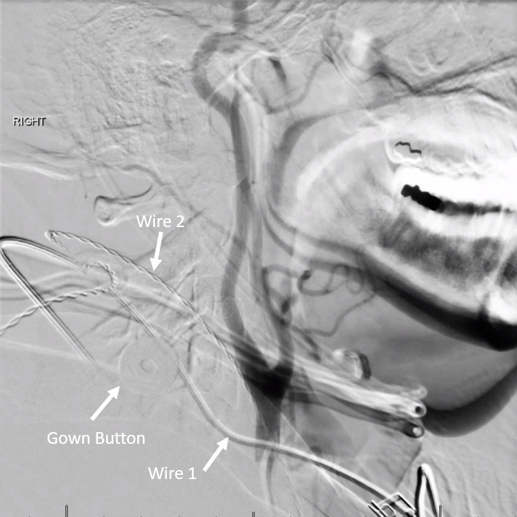
Here is our helpful ACLS Bill, showing what not to do…
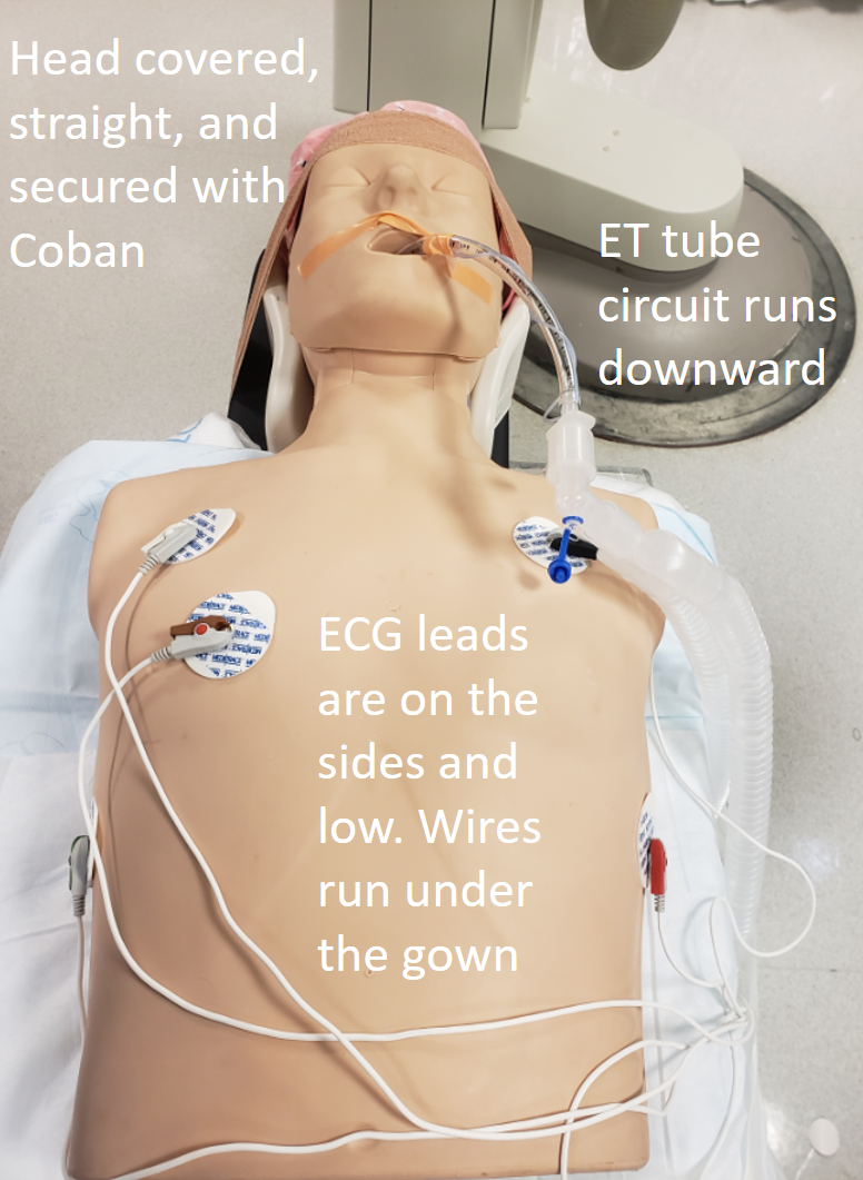
Here is the right way — especially those leads — run them on the side, down to abdomen, then cross over. ET tube circuit gets taped to gown or the velcro strap that goes over later.
Lateral view – nothing over or under the head, including those wafting in the breathe sheets…
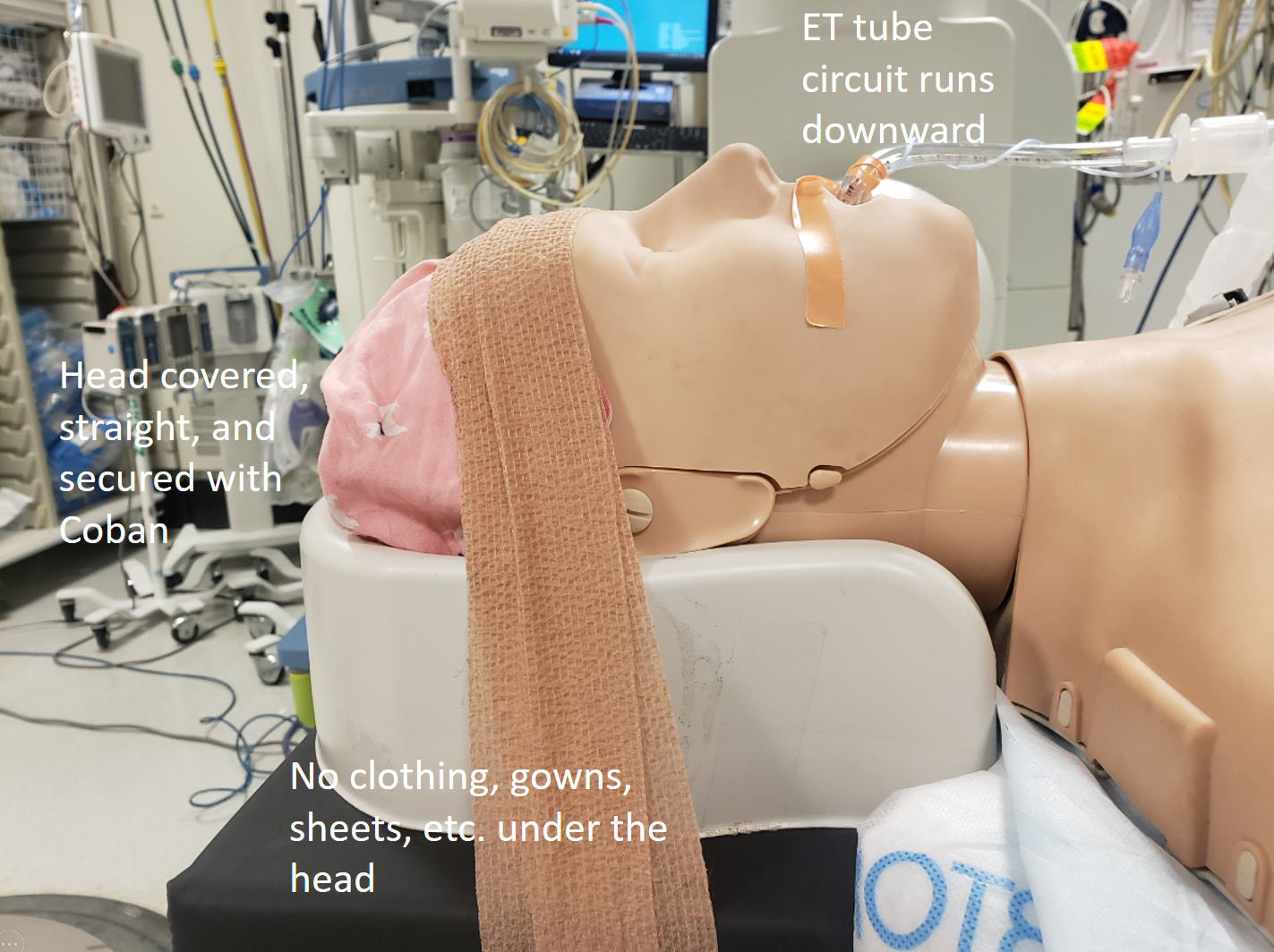
Both frontal and lateral planes are brought close to the head
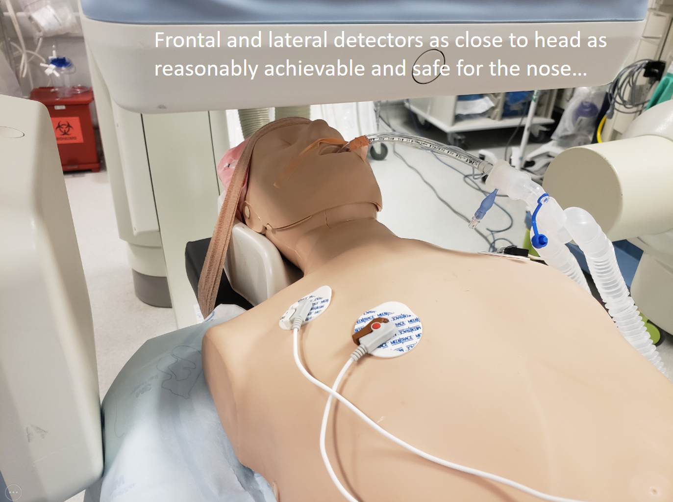
There are other tricks in this also — the most important message is to pay attention to this stuff if you want to have a professional image in the end
Airheads 🙂
A typical angio machine detector matrix is 512×512 pixels. This remains in place throughout the optical zoom range — for example, if we zoom in from the largest 48 cm field of view to say 42 or 22 or 11 cm, the resolution remains 512×512.
There is a common practice to include the entire head in angiogram, with a halo of air outside to boot. In most instances, however, one does not need to see the whole head when doing an ICA injection — only enough to see the ACA if there is a dominant A1. A too-high field of view reduces the resolution of the angiogram by only utilizing part of the detector for useful information. In the image below, white arrows are floating in the air — all those pixels are wasted. Image on the right shows an optimally magnified image.
Don’t feel like this is good advice? Still want to see the whole head? Fine — in this case, consider collimating to reduce your own exposure… Like this:
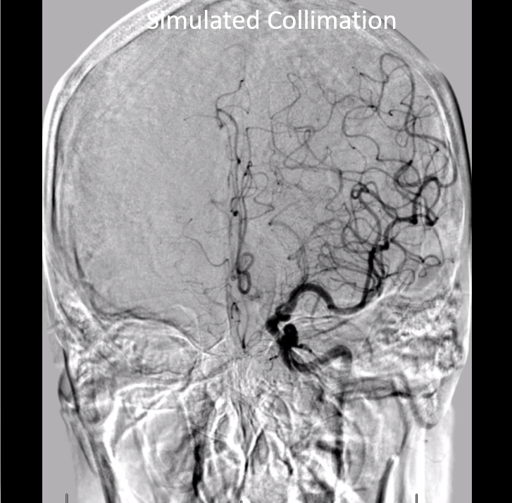
Of course, we don’t want to cut off / exclude anything important. The most common place to be excluded is the top of the head. In our multi-problematic image, despite including the unnecessary air, the operator did not show the vertex (black arrow), resulting in cutoff of the superior sagittal sinus, for example
Imaging the Basilar — hemodynamics
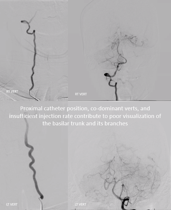
A common error is not injecting strong enough to adequately fill the basilar artery when co-dominant vertebrals create a scenario of competing inflow. The solution is to position the catheter higher in the vert (not at the ostium) and inject strongly enough to temporarily overcome the inflow of the other vert. Sometimes that’s very important — one sees multiple runs, none of which adequately show the basilar. Below is an example
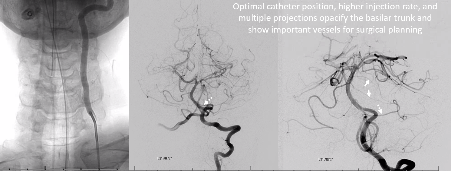
Same patient — catheter higher in left vert, higher injection rate — adequately showing low position of left AICA (dashed arrow), associated with two larger caliber pontine perforator vessels (white arrows) in this patient with a large petroclival meningioma. The basilar vessels are displaced posteriorly — draped on back side of tumor. All of this is important pre-surgical information
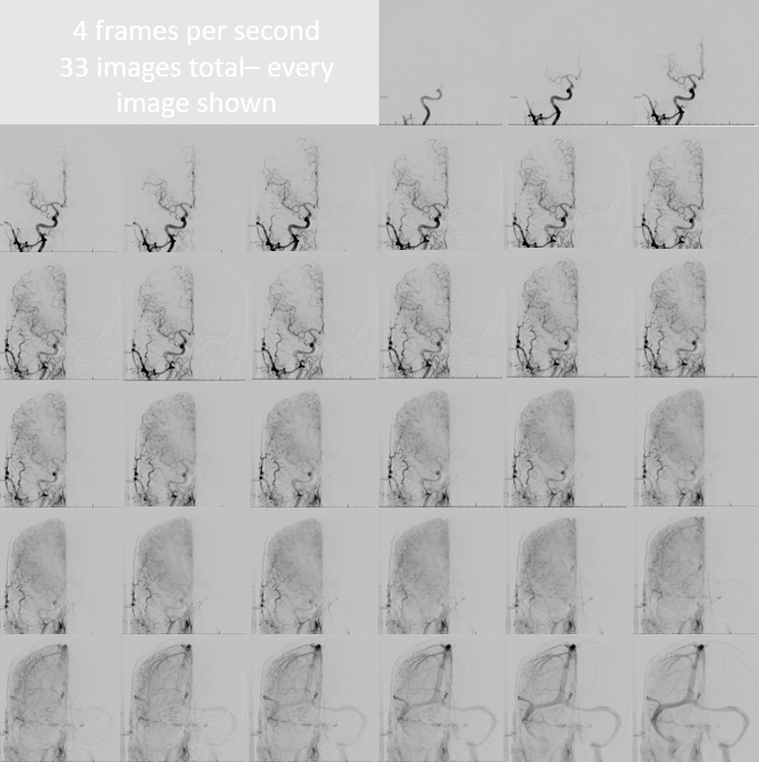
Frame Rate — DSA
There is a lot of variation here among operators. Many don’t really care what their rate is — whatever is set by the manufacturer is fine… Among those that do care, some like variable frame rates — like 2 or 3 per second early, then 1 per second for later venous phase. Others like constant rates. When latter is the case, the rate is often set at 3 or 4 frames per second. In our experience, this is unnecessarily high. A 2 frames per second rate is perfectly sufficient 99% of the time. When necessary, frame rate can be increased to work something out, and then dropped back to baseline.
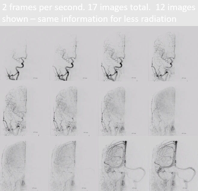
There are other factors to consider. Modern machines are capable of very high DSA frame rates — 15 fps for example. However, increasing rate comes at price of decreasing resolution — a 4 fps frame is not as crisp as a 2 fps one, usually. So, a 2 fps vs. 4 fps DSA is an all-round win — more information, less radiation. Here is a 4 fps series, with each image filmed
Here is the same patient, at 2 fps, and only 12 of 17 acquired images filmed. Nothing is lost, and unnecessary radiation is spared.
Technique — imaging all vessels you came to image
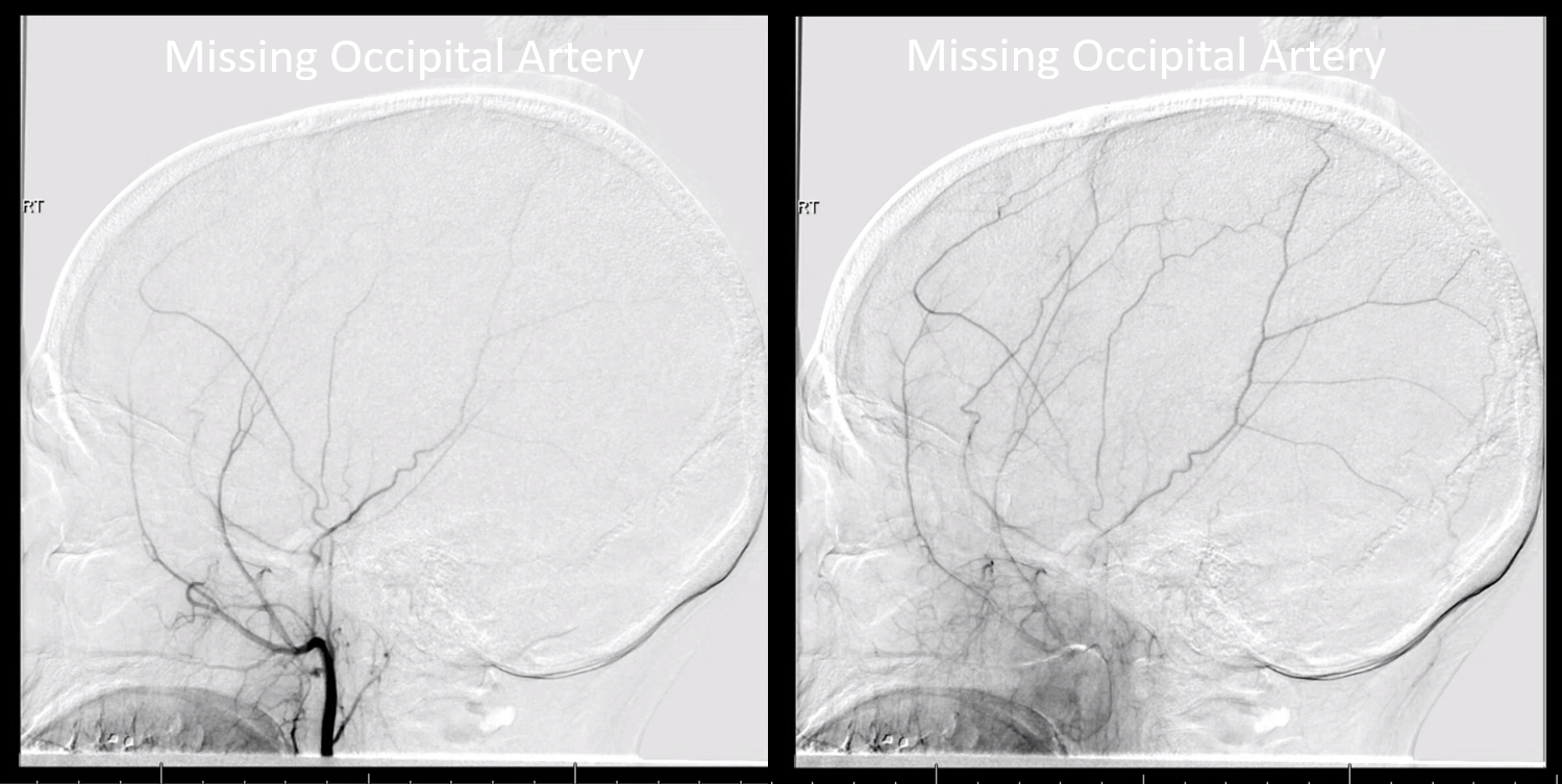
This can be a very long section. However, we will point out some common problems. One aspect is technical — intending to image a vessel but not doing so without knowing. For example, in the external carotid injection below, the catheter is too high up the external — beyond the origin of occipital artery which is this missing. The indication was pulsatile tinnitus and angiogram was done to look for a dural fistula. Obviously this is not an artery we want to miss here
Another common problem is not injecting all relevant vessels. This is more of a conceptual than technical issue, but still very important to cover. This patient presents with a left cerebellar hemorrhage
The angiogram includes right CCA, left CCA, left ECA, and left vert injections, identifying a tentorium cerebelli fistula (arrow) supplied mainly by the left occipital artery (open arrow)
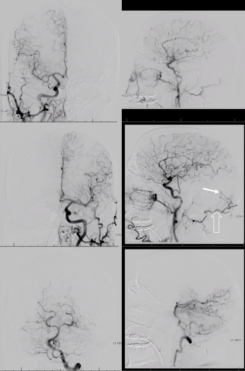
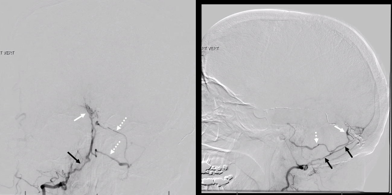
The right vert is not injected — and is in fact a major supplier of the fistula via artery of the tentorium cerebelli (black arrows, images below). It just happen to come off the right vert. The parasagittal Cognard IV fistula drains directly into left cerebellar veins (dashed arrows), with corresponding left cerebellar venous hemorrhagic infarction — which is no reason not to inject the right vert. For those interested in tentorium cerebelli fistulas, check out case archive page
The consequences of poor technique are of course multiple. The patient below had 2 spinal angiograms to look for source of tremendous cord vascular congestion — both times nothing was found. Only when this patient subjected herself to a third spinal angiogram in a different institution was a spinal pial fistula — supplied by not one, but two pedicles — both missed twice — finally identified. Full case is here
MRI
A spinal angiogram was done — illustrating exactly how not to do it. Awake patient, tilted body, no labels, no venous phase
When catheter is not optimally engaged in the vessel, it does not count
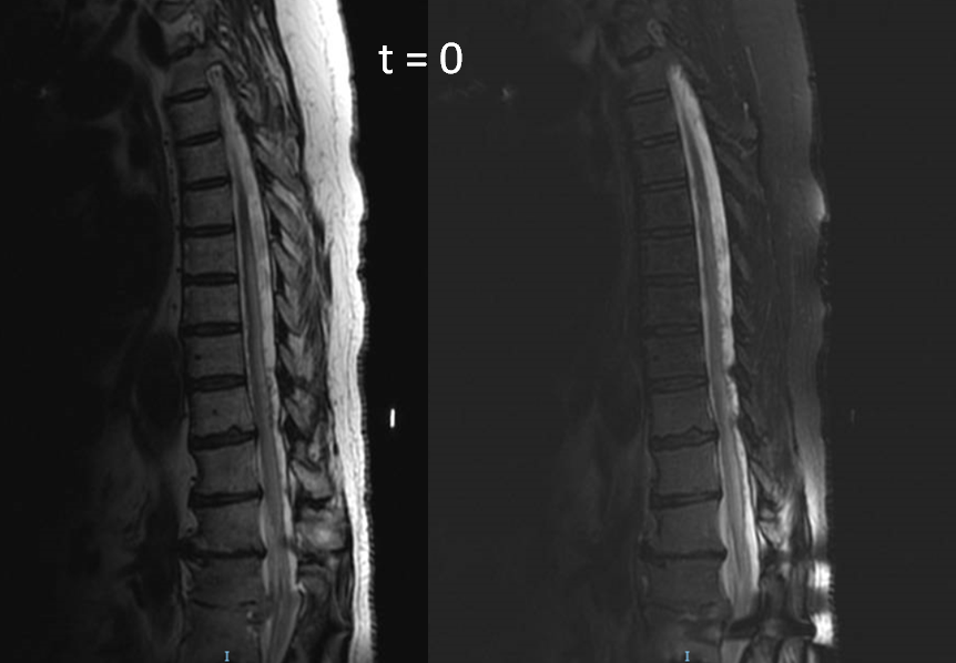
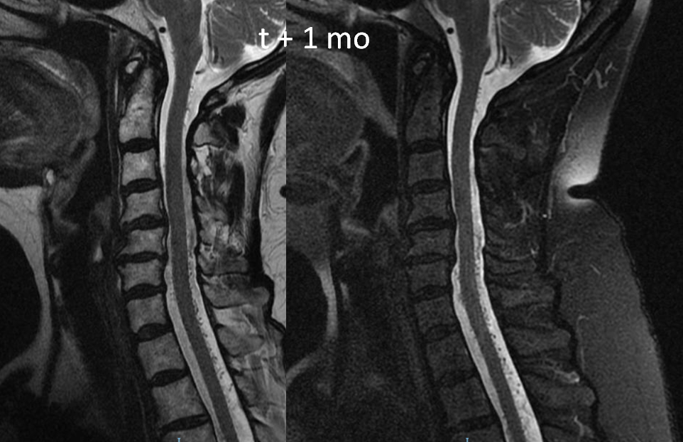
In all, 5 levels were not injected and nothing was found. A high resolution MRI was done however 1 month later to look for fistula level. The images are very nice
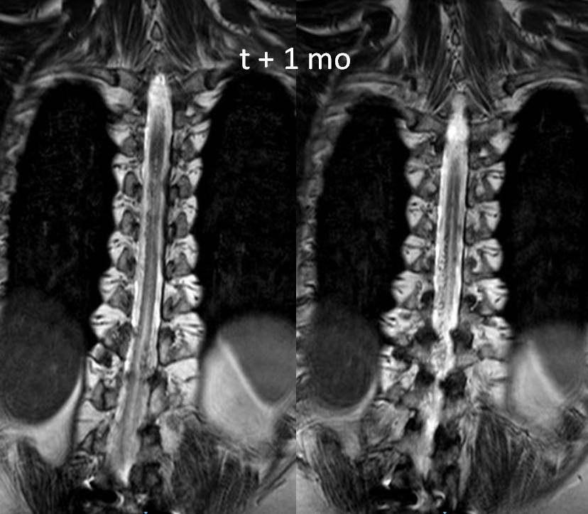
Sagittal shows extent of venous congestion
Another spinal angiogram was then done, and again nothing was found. The image below was correctly interpreted as anterior spinal artery. No venous phase images of this injection were done
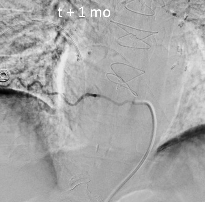
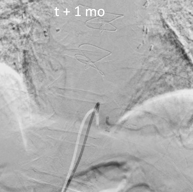
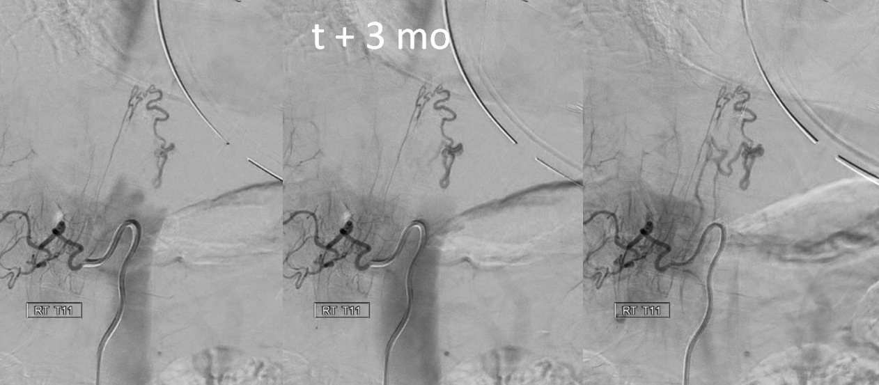
Finally, the patient came to a place that knows how to do spinal angiography, and very quickly a shunt is identified from right T11 level
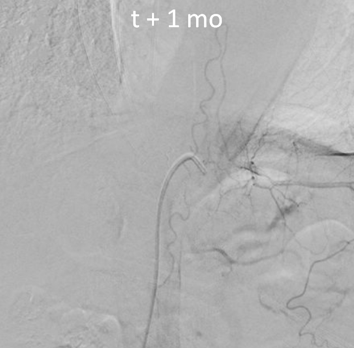
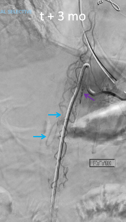
A better image of left T10 level shows that anterior spinal is in fact not normal. There is a shunt just medial to the catheter tip (purple arrow), and an early vein is visible (blue arrows).
The full case, which is very instructive for reasons other than poor technique (it is a pial fistula mimic of a dural fistula), is here
Imaging
Again, a big topic. So, just a few common points.
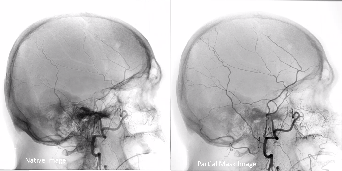
Including Native / Unsubtracted Images
Many angiograms are filmed without any unsubtracted images. It makes it rather difficult to identify bony landmarks or implants, unless same images are also degraded by motion. So, if you have a very nice image like this one (notice one problem — labels are missing)
Try to add an unsubtracted one also. Notice how the fully unsubtracted image on the left has some “white out” areas due to high contrast spectrum (for example over the nasal region). Solution is to image a “partial mask” image on the right, where both the bone is optimally shown and vessels are also preserved