
This section covers, in depth, the Pipeline Flex delivery system, and Pipeline Flex deployment. It is the second portion of the overall Pipeline Embolization of Cerebral Aneurysms topic — the first section reviews the Pipeline device, its geometric and physical properties, and other information essential for its optimal use.
A note of disclaimer can’t be avoided here — as you probably know, for 10 Pipeline operators there are 20 opinions on how to do it right. This is natural and expected. What follows is our way — I can only say that it works well for us.
CONTENTS
Resheathing Distal (Leading) Edge of Device
Delivery
Advancing Flex to Desired Position
Recapturing Distal Delivery Wire
Post Delivery — Checklist and Things Still Left to Do
Troubleshooting Guide — Difficult Situations
The answers to how a device should be deployed in one scenario and modified in another, why deployment sometimes fails, how to remedy a given problem and how to avoid another one, are found by considering the interaction between the patient’s unique anatomy, the device, and its delivery mechanism. It is therefore as essential to understand the delivery system as the device itself.
Below is an image of the Pipeline Flex delivery system components:

Any braided device, such as the PED, is housed within its delivery system by elongation, and thus foreshortens during deployment. In the image above, the device is housed between the Polytetrafluoroethylene (PTFE) sleeves and the resheathing pad — quite a longer distance than the unconstrained device itself.

An x-ray of partially deployed device:

Below is an image of the delivery system, as per the Instructions For Use (IFU). The terminology used for various components of the device follows the IFU.

IFU image with corresponding photos of delivery system components:

The leading edge of the delivery system consists of the “Distal Guidewire”. It remains 15 mm long, as in Pipeline Classic, which is useful to know as vessel length measurements are sometimes imprecise, especially when curvatures are involved. Its distal tip is curved to (hopefully) avoid inadvertent entry into a small vessel during device deployment. Unlike Pipeline Classic, it cannot be manipulated by torquing the delivery wire. Therefore, one should be especially cognizant of guidewire tip location in terms of its possible entry into perforators and other unintended targets. Although not recommended in the IFU, it is now possible to change the shape of the guidewire (don’t try it with Classic). This is done by advancing the device partially out of its protective sheath, like so:

Do not overexpose the wire so as to not accidentally “deliver” the PTFE sleeves. Next, gently shape the wire as necessary (usually, a very tight curve is what’s needed to avoid the problem).

Gently re-sheath the wire into the protective sheath, and re-shaping is done. I would not advise that this maneuver be done routinely — one scenario would be when guidewire issues required removal of a prior device, and the same problem is anticipated.
Distal Marker: Distal Device Protection (PTFE Sleeves)
The edges of the Pipeline, which are made by cutting the 48 wire braids comprising the device (each braid is 30 micrometers in diameter, see first section for details of PED design) are delicate and easily damaged. The advantage of this design is a versatile, homogeneous nature of the implant, without points of solder or relatively bulky markers that have the potential to prevent full device apposition to the parent vessel and complicate creation of multi-device constructs. The disadvantage is the need to protect the leading and trailing edges during their advancement within the delivery microcatheter. In the Pipeline Classic delivery system, this was accomplished by the Capture Coil, underneath which the device was held. The extent to which the distal edge was inserted into the coil and the mechanical interactions between the coil and the device determined the ease or difficulty of the device detachment from the coil. Such detachment could be facilitated by torquing the delivery wire and thus rotating the capture coil from the implant. When it worked, it worked well, however consistency in uneventful detachment was difficult to achieve and, furthermore, the capture coil needed to be re-captured into the delivery microcatheter, which was not entirely straightforward.
In the Flex system, the function of the capture coil is served by two PTFE sleeves, which protect the leading edge of the Pipeline. The sleeves are manually shaped and held in place on the delivery wire by the distal radio-opaque marker, which is soldered to the wire. The sleeves are about 2-3 mm long (1.7-3.4 mm to be exact), and are usually closer to 3 mm. Here is an image of the PTFE sleeves and the PED within the introducer sheath
In this sequence of photos, a 4 mm PED is delivered into a 3.0 mm ID tube. The sleeves have been partially exposed

In the following photo, the sleeves are free from the Marksman. The distal end of the implant has not yet fully expanded to appose the wall of the target vessel. Although it might appear that the PTFE sleeves are the primary cause of PED non-expansion in this photo, the appearance is deceiving. Rather than the sleeves, it is the geometry of the device itself that does not allow for immediate full expansion (unlike a laser-cut stent, such as Neuroform, which will spring open as its links are exposed).

As the following photo shows, approximately 8 mm of this 4 mm diameter device must be exposed in order for its leading (distal) edge to fully expand and appose the wall of the undersized 3 mm target “vessel”. A properly sized 4 mm vessel would take even more device

At this point, continued delivery produces good apposition of the device to the parent “vessel”, and the sleeves move forward, away from the leading edge

One strategy to remove the potential contribution of the PTFE sleeves to non-expansion of the device is to re-sheath the Pipeline, which will either flip the sleeves forward or place them underneath, rather than over, the device, as shown in the following photo. Notice that one of the sleeves does not “flip” forward, and will be resheathed together with the Pipeline, as happens occasionally in vitro at least. I do not feel that the vector of blood flow is strong enough to always prevent this from happening in vivo

Here, the device is fully resheathed into the Marksman

It is important not to withdraw the device too much into the Marksman, as the subsequent re-deployment will require pushing the now unprotected leading edge through the Marksman, causing potential damage (see below).
Here, the same device is re-deployed. Notice that even though the sleeves are no longer overlying the leading PED edge, re-expansion still does not take place immediately. Certainly, the device opens than with the sleeves overlying it. Nevertheless, as can be seen in the following photo, the device cannot possibly fully open upon immediate exposure. This is a common property of all braided devices. The ratio of exposed length to % opening depends on many factors — braid material, thickness, pitch, number, friction, etc. For this 4.0 mm diameter device, 5 mm of exposure will result in opening to 3 mm — target size of this “vessel”. A more appropriately sized 4 mm vessel takes about 6 mm of exposure.

Continued delivery produces full apposition by 6 mm

Not all devices will behave the same way. Larger diameter devices, for example, have a tendency to open more gradually (all devices have 48 braids of 30 micrometer wire, regardless of diameter). Sometimes, this results in the the distal end opening somewhat suddenly, almost in the same way as classic did when released from under the capture coil. This sequence of images shows the opening of a 5×20 mm device. Notice the long length of exposure (14 mm) needed for the device to release, the manner of its quick release, and the 4 mm “snapback” when the distal edge comes off the PTFE sleeves. This behavior is very similar to classic — with the advantage of more predictable eventual PTFE sleeve release compared with the capture coil.

When the same device is re-sheathed, and re-delivered without the PTFE sleeves overlying the leading edge, expansion is notably different, with a more direct relationship between exposed device and opening diameter

Lest you think that these images are bench-top only phenomena, here is a movie to prove that exactly the same behavior can be seen in vivo:
Resheathing Leading Pipeline Device Edge
The ability to resheath and re-deploy the device is a milestone in Pipeline delivery. When properly performed, it allows for repositioning, particularly when precision is needed in placement of either the proximal and/or distal device edges, and possibly enhancing opening of the distal device, as seen in images above. Now the position of the proximal edge can now be more fully controlled.
Caution: the user must be aware that re-sheathing the entire device will result in the delicate leading edge no longer being protected by the PTFE sleeves during re-deployment. This edge may be easily damaged under the following circumstances:
1. Excessive re-sheathing, so that re-deployment of the device requires advancing the unprotected edge thru the delivery catheter. When this happens, the re-emerging device may look something like this:

Delivery of such a device will produce an uneven leading edge

2. Pushing the partially opened, unprotected edge forward (pushing wire, loading, etc.) particularly into curved vessel segments or other circumstances where the leading edge would be susceptible to damage, may have unintended consequences. If not properly done, the edge may be become partially or wholly folded or caught, resulting in an appearance like this:

Below is an en-vivo equivalent of the above scenario:

The in-vivo equivalent is shown here:

Caution: Sometimes, one will encounter the “trumpet” appearance, as seen above, upon initial unsheathing, with no apparent user error. Essentially, what happens is that the device forms a “cornucopia” (distal white arrows), and fails to expand, forming a stenosis (proximal pair of white arrows). Here is an example; no user error was apparent:

This is particularly true of larger diameter devices — the 4.75 mm and 5 mm devices have this issue occasionally. “Wagging” the device, and sometimes pulling back on the device, can solve the issue. In other instances, nothing works, and the device must be either removed or distal aspect balloon-expanded after delivery. This is particularly important to consider when delivering on a curve, as discussed below.
As a rule, unusual geometric factors such as tight curves will tend to make any maneuvers more challenging. Deployment along curvature is one such factor. However, even when deploying device in a straight segment, it is important to make sure that the distal end fully opens before one comes around a tight curve. Otherwise, the device will tend to open and appose the vessel along the curve, while continuing to be inadequately expanded distally.
Here is an example of a device which has been re-sheathed, unsheathed, with a persistently unexpanded distal end (white arrows) — the so-called “cornucopia” appearance. Black arrow points to Marksman distal marker

If one continues to deliver the device, without addressing the distal end issue, the device will expand and appose the vessel along the curve, and remain unexpanded distally, like so (arrowheads point to expanded device apposing (almost completely) the anterior genu wall:

Here is another example, with distal end (white arrows) not fully expanded; unexpanded device is also noted at the anterior genu (black arrowheads). The Marksman marker is shown by black arrow

Continued delivery (Marksman black arrow marker further proximal) predictably results in apposition of the device at the anterior genu (black arrowheads), while the distal end remains unchanged. There is now a very tight stenosis (lower set of white arrows).
At this point, one can either resheath the device to try to open distal end, remove it, or deliver the rest and J-wire or balloon-expand the distal end. Given the degree of stenosis at the genu, we chose to remove this one.
Here is an example of a “cornucopia” we chose to balloon-expand.

A short, compliant balloon is usually sufficient, though one will sometimes rupture, especially when expanding at the edges, so make sure there is not an overly large air bubble inside. Noncompliant ones are stiffer and may “bump” the construct into the aneurysm, or straighten it out beyond what is desirable.
Summary
To optimize delivery of the distal device, consider the following recommendations:
1. Be aware that 7-14 mm of the device may need to be exposed before full expansion of the distal end
2. Resheathing distal end to “flip” PTFE sleeves out of the way may not result in dramatic improvement of distal end expansion. Continued delivery may be equally efficacious
3. Delivery on curves complicates distal end expansion, and may result in partial non-expansion
4. Avoid excessive re-sheathing of the distal end
5. During re-deployment of a completely re-sheathed device, pay attention to the now unprotected leading edge to avoid forcing it into a curve or other structure which is likely to damage the braid. Unsheath or otherwise gently re-expose the device until the distal end has fully expanded and is apposing its target wall before applying load
Below is a movie of deployment along a curve, using careful re-sheathing and re-deployment technique
Below is a movie of deployment along a curve without resheathing, assuring that distal end of the device opens before taking the curve

The 3 mm silicone pad (yellow in above rendering, amber-colored in reality) is mounted upon the delivery wire between the resheathing marker and the proximal device marker (see image below). The device is housed between the pad and the protective sheath, and during delivery between the pad and the delivery catheter (rendering above). Friction between the pad, device, and catheter allows for both deployment and re-sheathing.
The mechanism of resheathing by friction has two important implications. First, unlike Pipeline classic, the proximal (trailing) edge of the device is no longer pushed by the bumper; the device is extruded by friction of the resheathing pad. Therefore, the proximal edge is less likely to be damaged by the bumper, particularly when torquing was applied to free the distal edge from the capture coil in the classic delivery system. Consequently, the particularly problematic proximal device non-opening (the dreadful “comma”, among the worst kinds of issues previously encountered) has been virtually eliminated.
Second, because of the friction mechanism, greater importance is now placed on the precise dimensions of the resheathing pad and the delivery catheter. Too much friction may result in inability to either re-sheath or re-deploy the device. When this takes place, one may not be able to pull the device back despite significant force, or to re-deploy it. Damage to the delivery catheter may result as well. All manufacturing has built-in tolerance factors, and occasionally there will be outliers. This seemed to have been an issue early on, and is rarely encountered now. Because the resheathing mechanism has been tested extensively in the Marksman catheter, and not necessarily in other 027 models, it is probably best to stick to the Marksman, at least until there is data to support other approaches.
The bulk of resheathing is carried out by pulling (withdrawing) the delivery wire into the delivery catheter, rather than pushing (advancing) the catheter over the wire. The reason is because the Marksman (and other currently practical 027 catheters) lack sufficient stiffness to allow for such pushing. They will simply “accordion” somewhere along their length. Therefore, it is usually important to add some “load” to the delivery catheter (Marksman) before pulling on the wire to re-sheath the device. Otherwise, the entire system is likely to collapse proximally. The behavior of the device will dictate the extent of loading and re-sheathing required in each individual case. Below (A) is a typical example of “loading”, where Marksman is advanced enough for it to appose the outer curves of the siphon (black arrows). Once this is achieved, pulling back on the delivery wire will allow for resheathing without the system falling back, so that at the end of resheathing (B), the tip of the Marksman (white arrows) will be maintained in the same position

Adjustments may be required during resheathing (usually more Marksman load, especially if long segments are being resheathed)– so long as one understands the concepts, it is likely to be an uneventful experience.
Caution
Every once in a while, one will find that a device cannot be re-sheathed, no matter how much pull is applied to the delivery wire. Don’t keep pulling – fuggetaboutit. If one continues to pull, all that happens is that the Marksman will start to “accordion”, which looks like this (black arrows)

or something else will have to give. The issue of inability to resheath seems to take place under two circumstances — 1) excessive curvature, likely producing excessive friction to allow transmission of effective force to the device and/or 2) excessive friction between the resheathing pad and the delivery catheter. In either scenario, one will usually be able to continue delivery of the device, albeit without ability to resheath. Circumstances will dictate whether it is best to deliver the rest of the device or remove it. A stiffer delivery catheter than the Marksman would likely help minimize this problem, but probably at prohibitive sacrifice in navigability. One should appreciate that the Marksman is an amazing catheter, and seems to be functioning here at maximum of its potential. It is not surprising that occasional problems will be encountered.
DELIVERY
Advancing the Flex to desired position
The Flex delivery system is appreciably stiffer than that of the classic. One will notice this quickly, especially around tight curves. It is not, in my opinion, a major issue when treating lesions within the anatomical indication. Anything beyond ICA terminus is likely to undergo some straightening during delivery; the device itself is very flexible, and undue straightening of vessels is usually not seen post deployment. Also one should remember that, in young patients in particular, the supraclinoid ICA is rather mobile in general, and may be easily displaced by nothing more than a standard 014 wire (Transcend Platinum in this case) and a Marksman catheter. (The writing on the image is to discourage inappropriate use by non-professionals…)

Delivery of a stiffer system requires more support. Except in some very unusual circumstances, we use a tri-axial system (some kind of 6F guide, a Navien 058, and a Marksman 150 cm is the default). Two maneuvers will increase support:
1) More distal Marksman (black arrows) catheterization, particularly if anatomy is tortuous. This will allow the Flex to advance through a more proximal, sturdier part of the Marksman, and will leave room to maneuver if there are difficulties

2) Bringing the distal support catheter (white arrows), over the Marksman, as close as safely feasible to the site of deployment (anterior genu for a supraclinoid aneurysm, for example), creates substantial additional support

Here is a movie version of this:
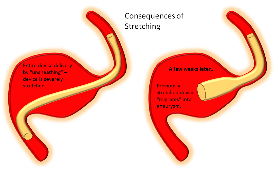
Delivery of the Flex is fundamentally similar to Classic. The bulk of delivery is done by pushing on the delivery wire rather than unsheathing the Marksman (as one would do with laser-cut stents like Neuroform or Enterprise). The reason for this is that the Pipeline, like all braided stent, is elongated within its delivery catheter. Expansion (delivery) is accompanied for foreshortening. It is better to push on the wire to allow the device to open and expand at the location of delivery rather than unsheath it, which would result in a stretched, incompletely opened device. Such devices are prone to foreshorten post-delivery — the so-called “delayed device migration”, as illustrated in the following cartoon:
Delivery – balance of unsheathing, pushing, and loading
It should be apparent by now that deploying the Pipeline is art as much as science. This can be used to your advantage. As an operator, you control how much you want to “pack” the device, when to add extra load, when to let it stretch a bit, etc. With increasing comfort comes the appreciation for the versatility and flexibility of deployment.
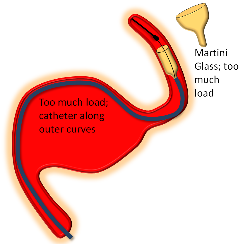
The key factor in delivery is appropriate load. Too much load causes the device to “bunch up” or even intussuscept, while too little leads to stretching. Like everything else there is a spectrum — within the “appropriate” amount of load there is ample room for variation of how much is desirable. The load is determined by the delivery catheter (and its proximal support) — pushing the delivery catheter generally increases load, and vise versa. The amount of load can be inferred by looking at the shape of the Pipeline device as it comes out of the delivery catheter, and by the relationship of the catheter to vessel and aneurysm walls, as images below illustrates. Increasing loads tend to push the leading cone of the device, which assumes a “Martini glass” kind of configuration, while delivery catheter is found along the outer curve, as seen below.
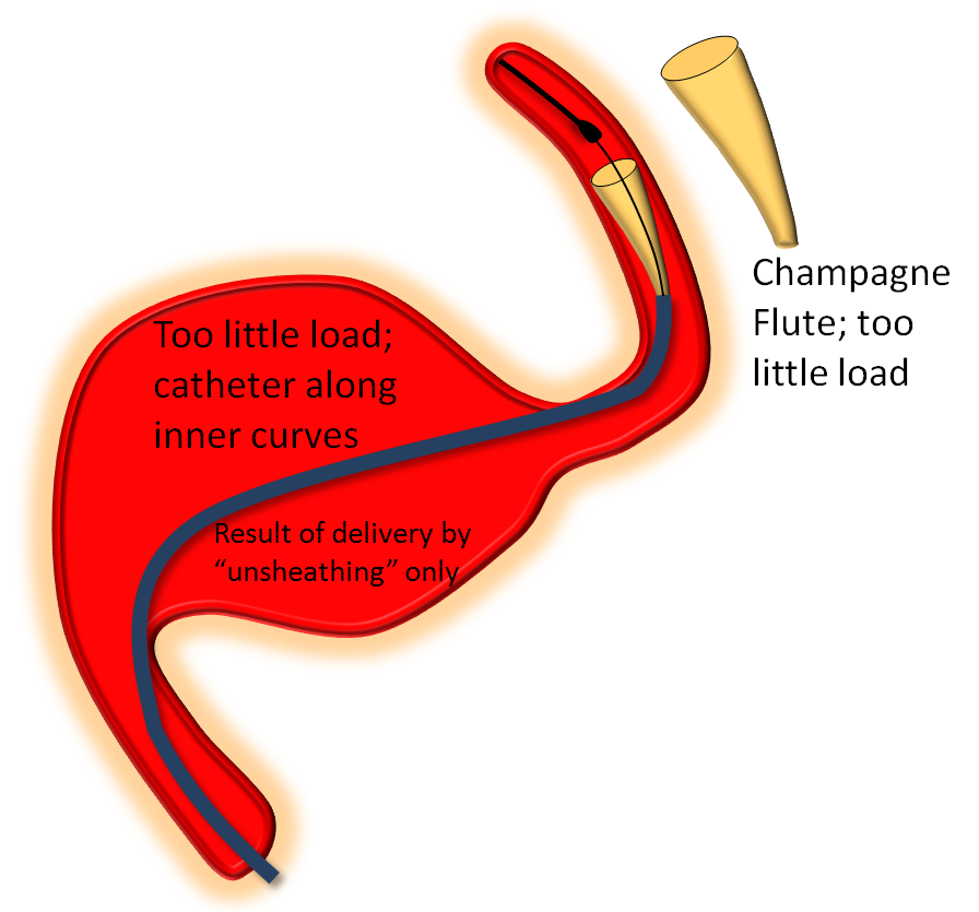
On the other end of the spectrum, stretching pulls on the leading edge which makes it look like a “champagne flute”, with delivery catheter situated on the inner curves, as also seen below.
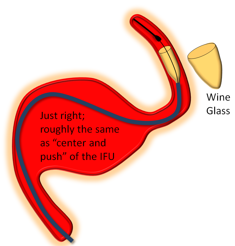
Somewhere in-between is what you probably want most of the time — a “wine glass” look, which roughly corresponds to the “center and push” look of the delivery catheter as stated in the Instructions For Use (have You read the field manual?)
This video of appropriate and inappropriate loads, from the Pipeline Classic page, applies equally to Flex
Distal Edge Retraction Upon Delivery
Remember that the distal edge of the device will retract (foreshorten) when it opens. This can result in the edge “slipping back” too proximally from the intended landing zone. Although the degree of retraction should be the same for flex and classic, in practice the degree of retraction or “falling back” seems greater for the Flex. It may be so because the distal end of device does not fully appose the vessel wall as quickly as Classic once the edge is out of the capture coil. It takes longer for this to happen with the PTFE sleeves. This is particularly true to larger diameter devices.
So, remember to position the Flex leading edge distal to where you actually want it to land, and allow for the “falling back” or foreshortening of the device. Especially for larger diameter devices like 4.5 mm and up. This only makes sense if you are not using “drop and drag” — I almost never use drop and drag because of increased risk of distal injury and limited ability to control the endpoint of the “drag”.
The following diagram from Pipeline Classic page applies even more to Pipeline Flex:

Flex Examples:
Below the landing zone chosen proximal to PCOM (A, white arrow) is actually too proximal. Device opens and slips back (B). A second device is deployed more proximally (C, D) to make sure there is adequate proximal landing zone coverage

Another example of how the distal (leading) edge (black arrow) retracts upon release of the device from PTFE sleeves at the distal marker (white arrow)

The result is inadequate coverage of the distal neck and landing zone. Positioning the distal marker at the PCOM ostium (white arrow) is actually too proximal, with the edge of the devive not adequately covering the neck (black arrow)

The device is resheathed (A, B) and re-deployed (C, D, E, F) to allow for adequate coverage

Threatened torsion and actual torsion, seen in the Classic version, are also potential features of the Flex system. The issue will predictably arise along curves. The most important factor is recognition. “Pancaking” — ovalization in one plane only (typically the lateral, when delivering around the siphon) is related to threatened torsion. Torsion is a figure “8” appearance of an actual twist, in all planes. Threatened torsion, if not addressed, can progress to complete torsion. Addressing torsion is similar to maneuvers with Classic — “wagging the tail”, delivery of slightly more device (if feasible), readjusting load are all maneuvers designed to redistribute forces leading to the torsion and thereby allow the device to expand. In our experience, resheathing and unsheathing typically does not help with torsion. We view resheathing as a means to reposition a device or, under some circumstances, to promote opening of the distal end. It is not, as a rule, effective in dealing with torsion or other delivery issues.
Once threatened torsion develops, it will often propagate proximally until full delivery is achieved. Fixing distal threatened torsion is likely to lead, upon further delivery, to foci of additional similar ovalization more proximally. In essense, one ends up “milking” torsion back to the proximal end, where the device will finally untwist. This is particularly problematic when long devices are being pressed into service along multiple curvatures.
Here is an example of torsion, in still life, under development (A, D), formed (B,E), and following delivery wire and Marksman manipulation to straighten it out (C,F)

If nothing works to undo the torsion, the device should be removed. Attempting to try another device of identical or nearly identical dimensions in hopes that it will work this time is, to paraphrase King Solomon, not a plan prompted by wisdom. Don’t do it. The right thing to do is to use several smaller devices in tandem to reconstruct the vessel. This will also have the advantage of multicoverage of aneurysm neck, nearly always an advantage (see first section).
Here is a movie of some threatened torsions we have come across. See Pipeline Classic page for some real torsions which we no longer allow to develop
Recapturing Distal Delivery Wire
Unlike Pipeline Classic, there is no capture coil to recapture. While this comes as a relief to many, there are some points to keep in mind. It is still best to recapture in a straight segment, to minimize friction and unfavorable angulation. Second, withdrawing the PTFE sleeves into the marksman takes a variable amount of pulling force, depending on the angulation, sleeve length, fold, etc. Gentle, contiguous traction works best. Remember Newton’s 1st law — the more you pull, the more the Markman will want to push back — or in this case the more it will want to jump forward once the sleeves are in. Anticipate this by:
1) choosing a segment where such a jump will not thrust the Marksman tip into something undesirable
2) reducing load on the Marksman, which will minimize the reactive jump. In other words, come off the outer walls of the parent vessel and stay along the inner wall.
Here are video examples of what are perhaps not the smoothest ways to do it
Don’t be counted with those who get out as soon as one device is deployed. There are still a few things to do, often those making a difference between success and the opposite.
Here is a post-deployment checklist:
1. Endoleak — assure adequate device expansion at all segments, with full apposition to landing zones, otherwise endoleak will result in treatment failure. Here, edge of device (black arrows) is not apposed to the wall (white)

The result is treatment failure (white arrowhead) at 12 months

Inadequate expansion should be addressed by J-wire technique or balloon angioplasty
We routinely use J-wire technique: the wire is shaped in steep, 180 degree J-like fashion, and run through the length of the construct, as shown in this cartoon:

This is how it looks in vivo

Here is a video of J-wire processing
J-wire technique promotes full device expansion and smooth inner contour at the leading and trailing edges. Care should be taken to keep the J-wire, especially if a stiff one is used, within the construct. The “one and done” camp, to which we do not belong, should be careful not to advance or otherwise dislodge their device into the aneurysm with this technique — especially when a large, fusiform aneurysm is being treated with a single PED.
Here is an example of how post-processing pays off, helping identify and address a somewhat occult proximal construct stenosis
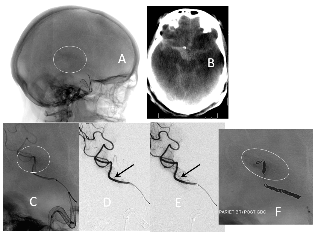
2. Embolus — use global frontal and lateral projections to check for emboli (white oval, arrows). Our advice is to only go after emboli with angiographically inadequate collateral support to the territory at risk. Remember, the patient is on dual antiplatelets. Whatever you do, remember that hemorrhage is much worse, so don’t risk one!

Active contrast extravazation (hemorrhage) is a dire situation on dual antiplatelet therapy and systemic heparinization. Sacrificing the bleeding vessel, quickly, may be better than loosing everything. The first step is to recognize the problem. Slow bleeds are subtle and may not produce obvious vital sign changes, as seen in images below. Notice relatively subtle opacity over the posterior Sylvian fissure (A, white oval) on an ICA injection, with corresponding microinjections (C,D,E) showing a small extravasation (arrows), which produced no small amount of blood and contrast in the subarachnoid space on this Dyna CT (B). The devices were already delivered, and so choice made to close branch with coils (F). Patient was recovered fully after 1 month (initial weakness).
If a distal branch is injured by the guidewire or catheter, it is probably best to close it if this is clinically feasible to avoid the risk of delayed re-hemorrhage. CC fistulas are unlikely to close with Pipe alone and will likely require coiling or some other treatment.
Is there adequate metal coverage of aneurysm neck? Individual treatment philosophies vary. There are opinions and publications on both sides. Our approach has always been geared towards multi-device neck coverage, when feasible, in line with methodology validated in PUFS. (see section on metal coverage). Aneurysms which remain un-occluded are often lacking sufficient metal scaffolding to allow for endothelial overgrowth. Here is one example, where a paraophthalmic aneurysm remains open due to lack of endothelialization at the distal aspect associated with single device coverage (B, C, D)

Troubleshooting Guide — A Handy Reference to Some Issues
Marksman Caught on Something (Ophthalmic) — try 016/018 wire like Terumo Headliner or Fathom, but carefully
Device will not advance through tortuous anatomy — bring support catheter (Navien) more distally, as much as feasible; use more distal Marksman catheterization, then release load to position the delivery catheters along the inner aspects of curves; re-apply steady push force; if all fails discard Device/Markmsan assembly, re-catheterize, and use shorter length device — navigability tends to increase quickly for progressively shorter devices
Device slips back from intended distal landing zone — resheath, advance past intended zone and re-deploy — leading edge will retract after opening; finish deployment, then deploy another device more proximally
Device distal aspect will not open: A “cornucopia” or trumpet of the distal edge forms, yet the distal aspect does not expand (see section above here). If this happens, wagging and gently pulling back on the partially expanded device may help. It often does not. The choice is either to continue delivery and balloon-expand the distal aspect, or remove the entire device. Do not choose to continue delivery unless you are confident that enough lumen exists in the partially opened device to allow for passage of a balloon catheter. A new user is probably better off removing the assembly
Device is not resheathing — release load to minimize curvature, apply steady pull force on wire; once resheathing commences, reapply load; tortuosity will make resheathing difficult; if uncomfortable, don’t keep trying and remove everything
Threatened Torsion — wag tail, deliver slightly more device, wag again, keep wagging, stop and wait a minute, wag again. Be patient. Resheath if actual torsion, re-deploy and address threatened torsion before it becomes complete. Only release entire device if comfortable with addressing threatened torsion near the proximal end. For persistent torsion, remove Device/Marksman assembly, re-catheterize and use several shorter devices to build a construct
Proximal Threatened Torsion — If only a few mm of device remain to be delivered, and there is threatened torsion, one can typically go ahead and deliver the device anyway. After delivery, device will typically untwist itself or, if this does not happen spontaneously, pushing on the proximal edge with delivery wire and Marksman will do the trick. Suggest doing this only when sufficient experience accumulates of if an experienced proctor / pipeline specialist is present to help
Device does not fully expand after delivery — use J-wire technique, which will be enough in most instances. If not, use a compliant balloon initially. Noncompliant (angioplasty) balloons should be reserved for cases resistant to compliant balloon dilatation. Careful analysis of images should be done to determine why compliant balloon failed to solve the problem — is there an underlying vessel stenosis, for example? A dissection? Will a non-compliant balloon risk damaging the vessel? Also, remember that non-compliant balloons are much stiffer than compliant ones — care should be taken not to push the proximal edge into the aneurysm in attempting to cross the device with a balloon. This is especially true for scenarios where a single device is used to treat a large fusiform aneurysm (our practice is not to limit ourselves to one device any more than we would, out of principle, stop coiling an aneurysm after one-and-done coil)
Can’t recapture PTFE sleeves/leading marker into Marksman catheter after device delivery — this is supposed to be easy without the capture coil, right? Not always. Sometimes PTFE sleeves have a hard time going back into the Marksman if the latter is positioned at a curve. Use a straight segment and reduce load on the Marksman to avoid a “jump” after PTFE sleeves finally go in. Apply steady pull on delivery wire in a straight segment. If uncomfortable with extent of pull, do not continue. Remove the Marksman and delivery wire together and examine them for why this might have happened.
Device not apposing landing zone walls — resist temptation to leave it like this! Use another device, in telescoping fashion, now appropriately sized :-), to make sure landing zones are fully apposed.
Distal thromboembolism — don’t over-react. Evaluate collateral circulation, eloquence of at-risk territory. Is there also clot on the Pipeline itself? Sometimes it is best to leave thrombus alone, rather than risking perforation with mechanical thrombectomy or hemorrhagic conversion with use of heavy IA artillery such as IIb/IIIa inhibitors or t-PA. If necessary to go after clot, use most compliant methods least likely to displace vessels and tear perforators.
Local thrombus formation — an immediate post-Pipeline deployment run demonstrating no aneurysm filling — apparent instant success — should raise concern that clot is quickly forming on the Pipeline, converting it to a covered stent. Don’t celebrate. Wait 10-15 min to see what happens. If clot formation is confirmed, intra-arterial IIb/IIIa inhibitors are highly effective. Be careful, especially if there is history of prior stroke/hemorrhage. Consider the possibility of allowing the vessel to close if there are adequate collaterals present, rather than risk a hemorrhage.
Intraprocedural hemorrhage — this is the time to act quickly. The best chance to save the situation is to stop the bleeding immediately. Emergent sacrifice of the bleeding branch should be strongly considered. If collaterals allow (good circle of Willis), there may be a viable option of antiplatelet reversal. Functional survival is possible in a minority of cases
Our practice is to perform 6,12 month, and 3-year post-procedure angiography, in accordance with PUFS protocols. Several instances of delayed (post-12 month) occlusions have been seen. Longer constructs may require lifelong antiplatelet medication. We tend to keep posterior fossa (especially basilar) patients on dual anti-platelets (empiric dosages) for life. Giant aneurysms fall into the same category. It is, otherwise, not the purpose of this page to comment on anti-platelet strategy in terms of choice of agent, monitoring, duration of therapy, etc.
No presently available MRA sequence allows for adequate visualization of flow within the stent, or identification of small residuals adjacent to the Pipeline device, in the author’s opinion.
CTA can be reasonable if a single device is used. Multi-device constructs become progressively more difficult to evaluate in terms of in-construct stenosis or small residual, due to beam hardening.
Disclaimer
I, Maksim Shapiro, am a Pipeline proctor and per diem consultant with Medtronic, which recently acquired Covidien, the manufacturer of Pipeline. No financial or other support whatsoever was provided by any legal entity, group, or individual towards creation of this page, or www.neuroangio.org as a whole. Pipeline devices featured in ex-vivo images above were donated by Covidien for general training purposes, and related projects. See Disclaimer section for general disclaimer information.
Questions/comments: Use “Contact Us” page, email me directly at neuroangio@neuroangio.org, or contact the office via link below:
(back to parent page “Pipeline Embolization of Cerebral Aneurysms“)