
CASES SPINAL DURAL ARTERIOVENOUS FISTULA
While cases can certainly illustrate important aspects of treatment, the focus on anatomy and pathophysiology will be maintained in that treatment aspects often underscore important anatomical considerations which ultimately translate into safety and efficacy of the intervention.
CASE 1
A middle-aged man, who presented with progressive lower extremity sensorimotor dysfunction and urinary complaints — typical symtoms of a spinal dural fistula.
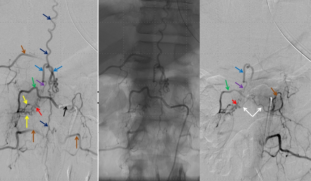
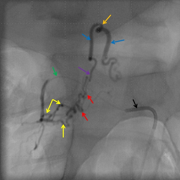
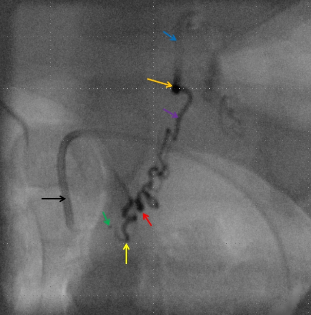
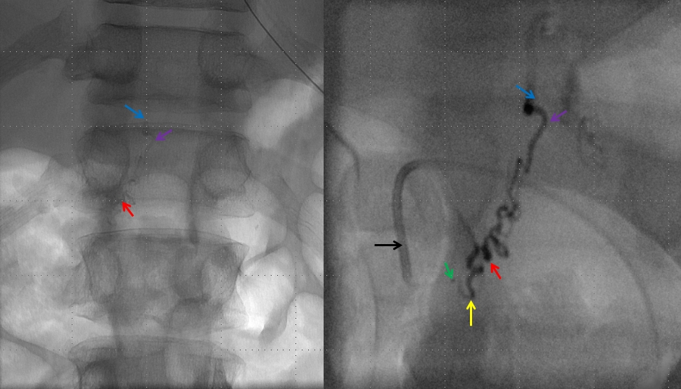
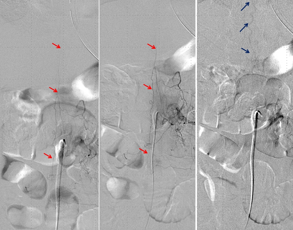
Left image shows a catheter (black arrow) in the right T12 segmental artery (green arrow), demonstrating a fistula (red) supplied by two separate pedicles (yellow) in the region of the nerve root sleeve. The earliest common vein (purple) leads into a tortuous probably intradural vein (light blue) and from there congests the spinal vein (dark blue). Notice also multilevel opacification of adjacent segmental arteries (brown) via the paravertebral network. The native image is shown in the center for reference. Image on right demonstrates opacification of the fistula via contralateral left T12 segmental artery via the paravertebral network (white arrows) collaterals to the right T12 segmental artery. Movie run of the same injection appears below.
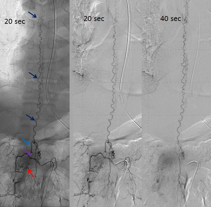
An open magnification view of the spinal column shows tremendous venous congestion secondary to lack of venous outflow from the spinal vein (dark blue), with only one radicular vein visualized at the upper thoracic level on a delayed acquisition of 40 seconds (rightmost image, vein adjacent to the letter “c”. Movie of the same run is below, where the draining vein can be seen to advantage. This run was acquired at 1 frame/second, instead of our typical 2 fps, so as to minimize radiation exposure and control tube temperature
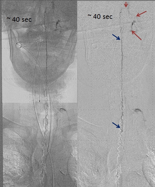
A delayed run of the craniocervical region finally shows drainage of the spinal vein all the way up in the head (brown arrows), in the region of the petrosal sinus, and another remaining left inferior cervical radicular vein (no arrows, see movie). This image illustrates the pathophysiology of SDAVF, whereby patient symptomatology is dictated not by the presence of fistula, but by progressive obliteration of spinal radicular outflow veins, which cause congestion of the spinal vein and spinal cord. Movie of the same run below
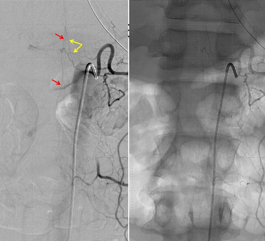
Injection of the segmental artery giving rise to the radiculomedullary artery (yellow) and the ASA (red) demonstrates no spinal vein on delayed aquisition, as seen in movie below. Usually, a spinal vein should be seen when a relatively large segment of the ASA is opacified. The spinal vein is not seen due to fistula-related congestion. In other words, injection of the ASA should be accompanied, in venous phase, by appearance of veins, as anywhere else in the body. Failure to see these veins is evidence of venous congestion — the spinal veins are taken over by the fistula. Movie of this run is shown below:
Microcatheter injection of the right T12 level, demonstrating the fistula (red) and its two contributors (yellow). We felt that optimal control for n-BCA glue injection would be best achieved by closing one of the two feeding pedicles and gaining a “wedge” position in the other pedicle, to allow for maximum control of the glue shot. The glue must reach the vein distal to the fistula (purple) in order for the fistula to be completely closed, but must not go into the spinal vein — or the outflow of the cord will be destroyed. For that reason we felt that our “safety” point was at the orange arrow, but ideally did not want any glue in the blue arrow portion of the vein, since it may be intradural and possibly might be used for cord drainage later — probably pretty conservative.
Attempts to selectively occlude the more superior pedicle were not fruitful — the microcatheter could be advanced into it somewhat but a coil could not be deployed and we did not want to risk a glue shot here and occlude our access to the other pedicle. Putting glue anywhere proximal to the vein (purple) without permeating the vein itself would only create an apperance of cure, while the fistula would remain alive and fed from other contributors, one of which was already seen from the contralateral left T12 injection. Therefore, the guidecatheter was advanced further into the segmental artery (black), and thereby occluded the more superior of the feeding pedicles. The microcatheter (green) was then wedged in the more inferior dominant feeder (yellow). The vein is marked in purple, and our ideal safety point lowered somewhat (orange)
Glue shot movie, permeating the fistula into the vein:
Static picture of the glue cast (left) with arrows corresponding to vascular structures as seen on the pre-embolization microangiogram. The glue is well within safety range.
Post-embolization right T12 view with guidecatheter still in distal position, showing no evidence of residual fistula. Control injection from the contralateral left T12 position shows no fistula either. The diamond-shaped retrovertebral network is seen as well.
Post-embolization injection of the ASA (red) now shows, in delayed fashion, the spinal vein (blue arrows) which was previously used by the fistula but is now utilized by the territory subserved by the ASA. This is the “money shot”, so to speak, more glamorous than the glue shot, even.
Movie of the same injection, below
The patient is improving.
Case 2 — Ascending Pharyngeal Artery origin Spinal fistula
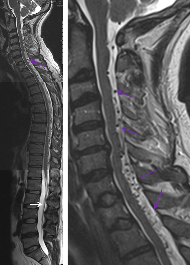
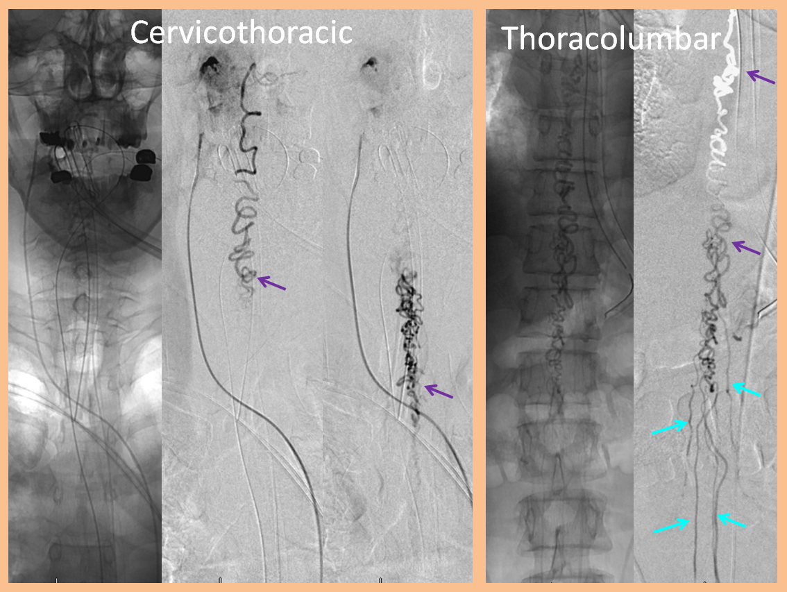
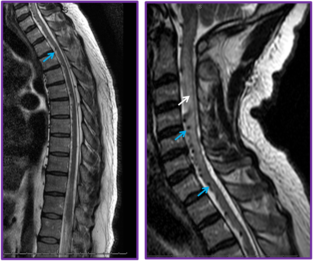
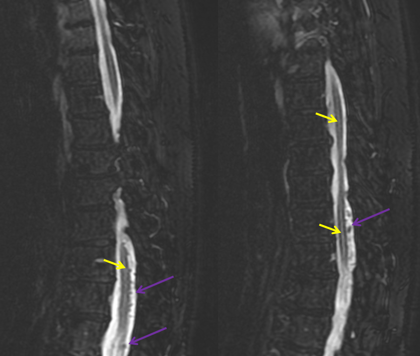
What typically defines spinal dural fistula symptomatology is NOT the site of fistula but the extent of spinal venous congestion, and venous mode of drainage. It is, in fact, a venous congestion disease, albeit with an arterial cause. Nevertheless there are sometimes clinical and MR imaging aspects that hint at something unusual. This is aptly illustrated in this case of a middle-aged man presenting with upper and lower extremity paresthesias — yet typically omnipresent urinary / bowel symptoms were absent. Composite MRI of the spinal column (left image) and cervical spine (right image) shows extensive congestion of the veins (purple arrows). Notice, however, that the conus and lumbosacral radicular veins are somewhat less prominent than might be expected for the degree of venous prominence (white arrow). There is also suspiciously little edema within the cord.
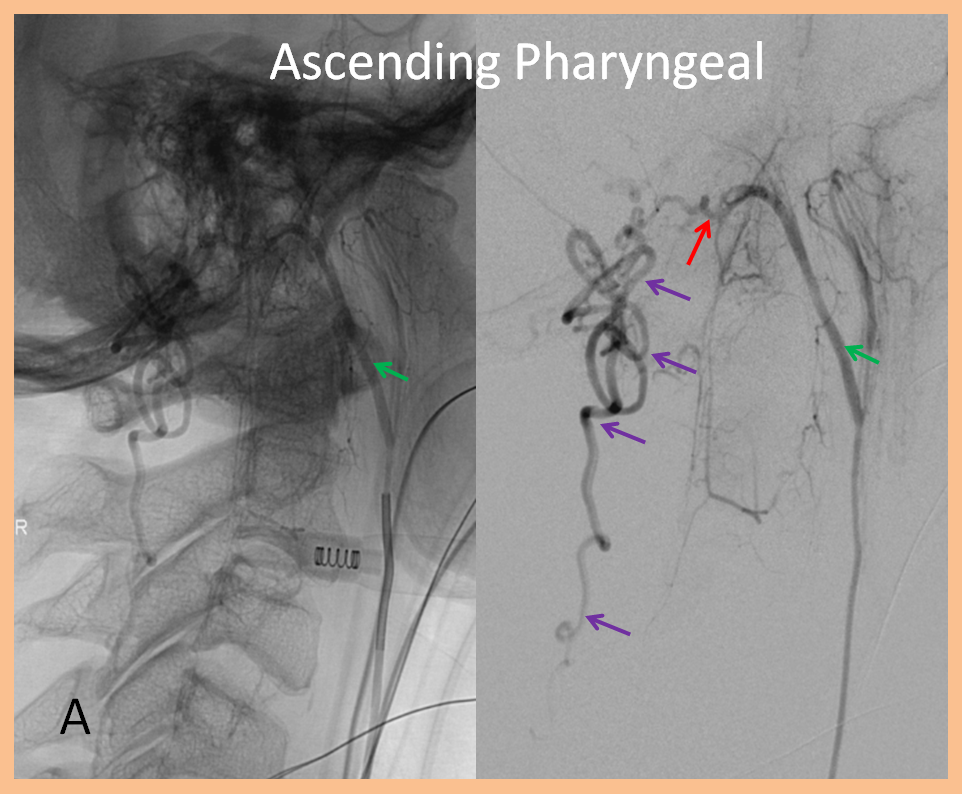
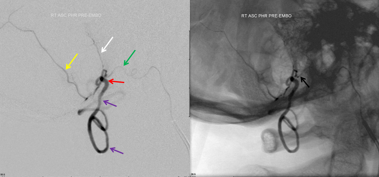
While the diagnosis of spinal fisula should not be in doubt (as sometimes unfortunately happens when the first spinal angiogram fails to uncover the fistula), there is something unusual about this one. In fact, the initial angiogram, including pelvic vessels, was “negative”. The fistula was found on repeat angiography by focusing on high-yield “second angio” vessels such as the ascending pharyngeal artery. The following images show a dural fistula (red) supplied prinicipally by the hypoglossal division (green) of the ascending pharyngeal artery, draining into the same dilated spinal veins (purple) as seen on the above MRI.
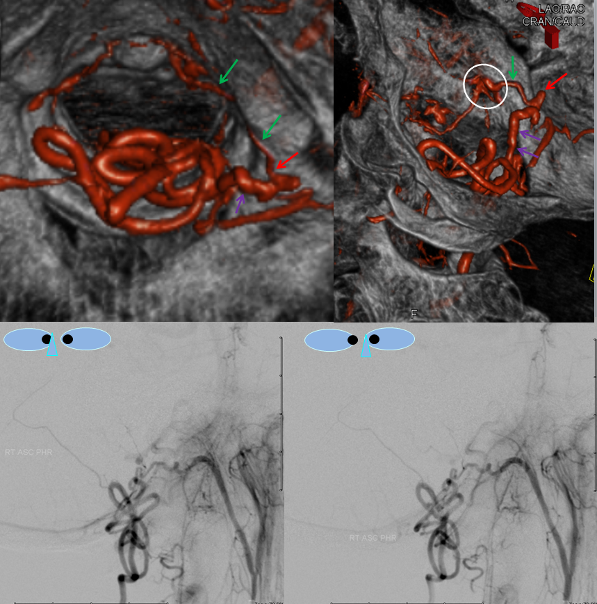
Images below show selected rotational 3D-DSA views “down the barrel” of the spinal canal (upper left), oblique dual volume view showing the hypoglossal canal (white oval circle) through which the hypoglossal division (green) connects to the fistula (red). Bottom images are an obligatory stereo pair. Notice reflux into small posterior meningeal tributaries to the fistula. This is an example of a “foramen magnum” dural fistula, which usually drains into regional veins of the posterior fossa and marginal sinus. This one, however, has no such drainage — only spinal veins are available (perhaps all others have thrombosed off by now) — it is therefore only an “unwilling” spinal fistula, so to speak.
Injections of the same ascending pharyngeal artery with delayed imaging over the spinal column show an amazing picture of tremendous venous congestion throughout the entire spinal venous axis, with only visible drainage via the radicular veins of the cauda equina (light blue arrows) !
Treatment images below show a Marathon catheter positioned as far as possible into the hypoglossal branch (proximal hypoglossal division embolization endangers the cranial nerve of the same name), achieving “flow arrest” or “wedge” position. Notice again branches of the posterior meningeal artery (yellow and white arrows) which define the common arterial channel. The fistula must be located distal to the confluence of these arteries — usually it is at the point of dilatation (red arrow). The glue must permeate the fistula without going forward too far into the vertical segment of the spinal veins, which may severely compromize the cord.
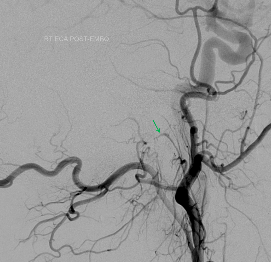
Post nBCA injection lateral projection view of the CCA shows preservation of the hypoglossal division proximal to the now closed fistula (green arrow). No reconstitution was seen from the posterior spinal artery (vert injection).
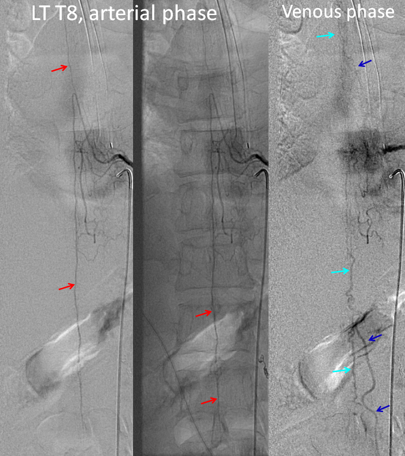
Finally, injection of the left T8 segmental artery giving rise to the Adamkiewicz (red=ASA) now visualizes spinal veins (light blue) in their appropriate venous phase, with lumbosacral and even mid-thoracic radicular drainage (dark blue arrows) — confirming that fistula-related venous congestion has been eliminated.
Upper cervical dural fistula with rapidly progressive myelopathy
Foramen magnum and cervical dural fistulas seem to be somewhat unique in their ability to very rarely hemorrhage, as well as to precipitate hyperacute clinical decline. I think this is related to the fact that, as seen in the above case, the drainage of the cervical fistula into dependent cord veins will involve essentially the entire cord. This is different from thoracolumbar level fistulas, which develop cephalad drainage in proportion to the degree of caudal venous drainage failure (see Spinal Dural Fistula page). In this sense, any compromise in caudal venous drainage of a cervical level fistula will abruptly endanger a large segment of the cord. This particular patient presented with acute onset of rapidly progressive (over 1 day) bowel and bladder dysfunction and ascending paralysis to the extent that about 24 hours from time of symptom onset he was having difficulty moving the upper extremities and felt short of breath.
MRI showed extensive edema (white arrow) in the cervical area with dilated venous channels (blue)
Vertebral artery injection shows fistula supply via branches of the odontoid arcade (purple) and C2 dural artery (orange). The recipient vein is blue, and an aneurysm ventral to the medulla is black. The area of the fistula itself is rather busy.

Injection of the ascending pharyngeal artery also shows its contribution to the fistula from the musculospinal branch (yellow), which subserves the area o the upper cervical spinal area (See Ascending Pharyngeal Artery). The fistula point (red) is determined by area of transition from many converging small dural branches onto a larger venous channel (blue), and is better seen here than from the vertebral injection. A venous aneurysm ventral to the medulla is shown in black. The fistula decompresses into anterior and posterior spinal veins.

Angiography of venous component shows its extensive congestion all the way down to the conus. It is absolutely astounding how a relatively small dural fistula can cause so much congestion. The reason is that the transdural venous egress is the weak link within the spinal venous system, and is easily overwhelmed.

The microcatheter (purple) is positioned within the odontoid arcade branch and skillfully navigated by Dr. Tibor Becske essentially to the point of the fistula. It is a perfect spot for glue injection, the closer to the fistula the better. The catheter is “wedged”, with forward flow control. Notice how injection allows for retrograde visualization of the musculospinal ascending pharyngeal branch (yellow), perfectly showing the convergence of these feeders upon the fistula point (red). The proximal recipient vein is blue, and the aneurysm is black.

Following glue injection, the odontoid branch will be closed. The “control” angiogram must be performed from another feeding branch — in this case both vert (C2 contributor) and ascending pharyngeal should be tested. Both show that the fistula is closed:

A CT scan of the cervical spine beautifully shows the n-BCA cast, with the different contributions of the ascending pharyngeal (yellow), C2 (orange) branches now filled with glue — the strategy for the cure is to fill the fistula hole, refluxing nBCA into the other contributing arteries. The point of the fistula along the dura (red) is now seen as a transition between multiple smaller arterial feeders and the larger recipient proximal intradural vein (blue). Notice how nicely the glue shows the C2 radicular contribution through the neural foramen.

The patient made an amazing clinical recovery.
Common radiculomedullary artery and dural fistula origin
There is no law against both the fistula and radiculomedullary artery origin from the same segmental artery, just as there are cases of radiculomedullopial artery (radiculomedullary and radiculopial artery common origin). In fact, there is a radiculodural branch at every radiculomedullary artery origin, and the radiculodural branch is to small to be seen, as it always is. Unless, of course, it is connected to a fistula…
This patient with progressive myelopathy and several spinal MRIs was finally referred to Dr. Jonathan Howard, an MS specialist at our center who knows better than writing “MS” on everything one doesn’t understand. MRI shows typical findings of extensive lower cord edema and surrounding vasculature. This cord does not enhance on post-contrast T1, but many do, usually in a patchy kind of way.
A thoracic aortic runoff, as usual. Unlike high flow pial fistulas, dural shunts are slow and therefore more difficult to see on an aortic runoff. The ones with this amount of cord edema are usually big enough, though.
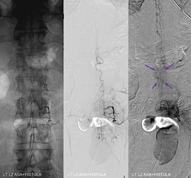
Fistula is found at the left L2 level, along with the Adamkiewicz (white arrows), arising from the same dorsal spinal branch (black). A VERY long bridging vein (purple) is present, finally decompressing into multiple spinal veins at the top of rightmost images (not labeled…). This entire bridging vein can be safely permeated with glue, up to the spinal veins, which would make it a rather straightforward case, except for the anterior spinal. Catheterization and embolization of the fistula carries what i consider a rather small but still unacceptable risk of catastrophic injury, especially when surgical options are available.
Another series of images, showing better the characteristic parenchymal phase congestion of the conus (purple arrows), with no visible draining veins.
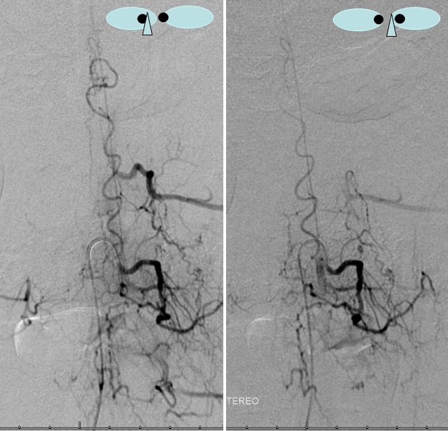
Stereo views are not simply cute. The are very useful in confirming that the long bridging vein undulates along the left posterolateral surface of the cord, with the anterior spinal artery serving as a stereo landmark of the ventral surface. This helps determine optimal surgical approach, which we choose in such cases instead of risking inadvertent radiculomedullary artery occlusion in an attempt at endovascular disconnection.
Venous drainage of the fistula must always be defined, in this case extending to the upper thoracic region, as is typical in cases of severe cord signal change on MRI.
In situations like this one, we feel that embolization is probably riskier than open surgery, where the bridging vein can be positively identified and disconnected (cauterized and divided) from the fistula. This patient was referred for open surgery.
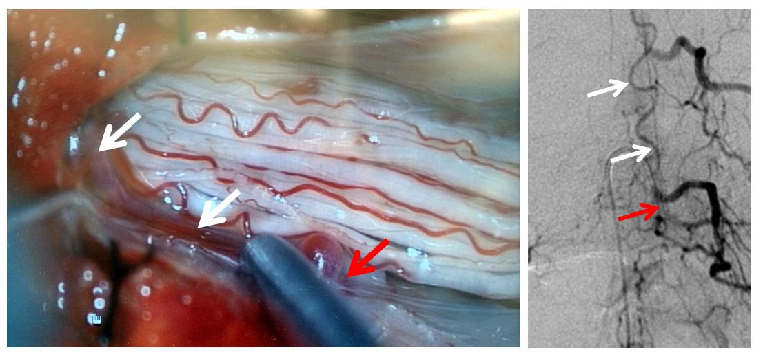
A single level laminectomy is performed, and the dura is opened, exposing nerves of the cauda equina, each of which is associated with a radicular vein (purple arrows). These veins are larger in caliber than they should be, due to fistula-associated congestion. The bridging vein (white arrows) is clearly seen in the left posterolateral intradural location, exactly as expected. The vein entry into the nerve root sleeve is marked by the red arrow.
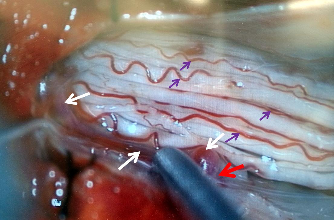
The same picture is shown next to the corresponding angiographic image:
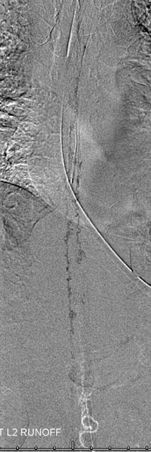
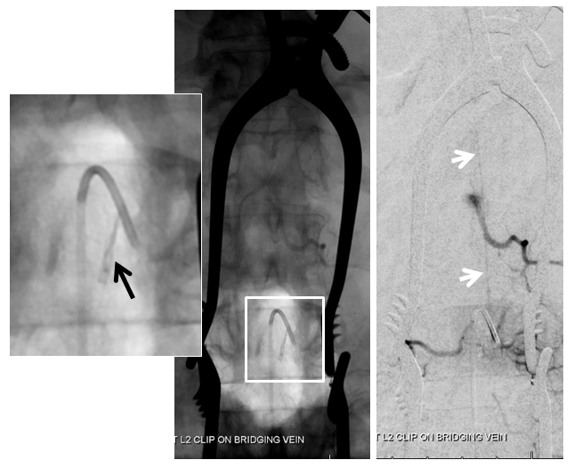
Next, a temporary clip (black arrow) is placed on the vein, and an intraoperative angiogram is acquired, confirming that the right vein was indeed clipped.
Intraoperative angiographic confirmation of bridging vein occlusion is obtained. Clip is marked by black arrow. The radiculomedullary artery is intact (white arrow):
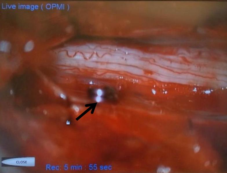
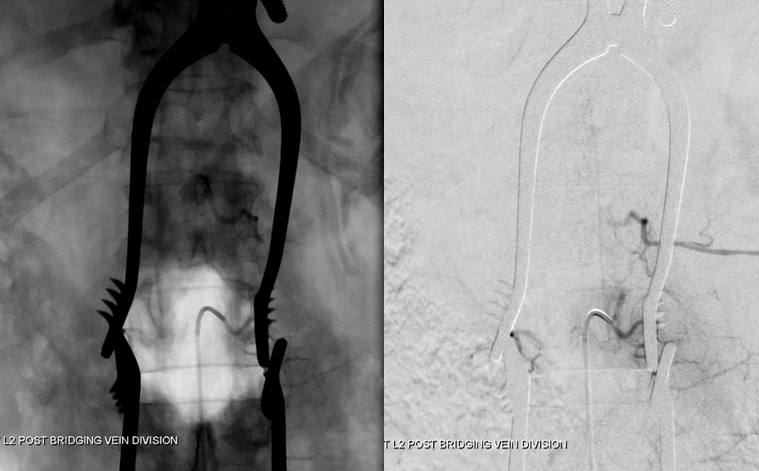
Following confirmation, the vein is cauterized and divided as close to the entry into the nerve root sleeve as comfortably feasible. The fistula is cured, as shown in this final intraoperative angiogram:
A segment of the intraoperative video is shown:
Note: Surgical portion of the procedure performed by Drs. Donato Pacione and Anthony Frempong-Boadu of NYULMC
CASE 6
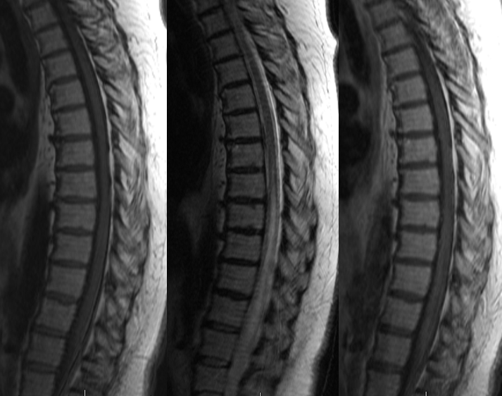
A woman in mid-sixties with progressive sense of leg weakness due during walking after about 15 minutes, resolving with rest, mild urinary incontinence, and sensation of heaviness in the gluteal area. Normal neurologic exam (sensation, motor, tone, reflexes, etc). MRI of thoracic spine, lumbar spine, and myelogram were available. Classic MRI appearance of dilated veins surrounding the cord (purple) with cord edema (yellow).
Not typical to have a myelogram, but since the process was not recognized on the MRI she got one — same dilated veins (the lower arrow is off target on the lateral)

Aortogram demonstrating a relatively high flow fistula seen well in late arterial phase, and persisting into later phases.

The fistula is found at left T10 segmental artery

A video of the same injection, in demagnified frontal projection:
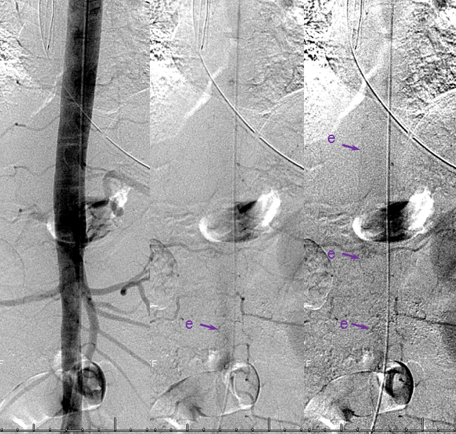
Unlike most fistulas, this one has predominantly caudal drainage, which means that at least one radicular / bridging vein must be functional down below. This must be followed angiographically to see where and how the fistula eventually drains. Images below show drainage via the right L5 emissary vein (pink arrow), the single major remaining outlet.

Video of the same. The catheter is off the screen, with long drainage towards right L5:
Same video in full DSA, for better visualization:
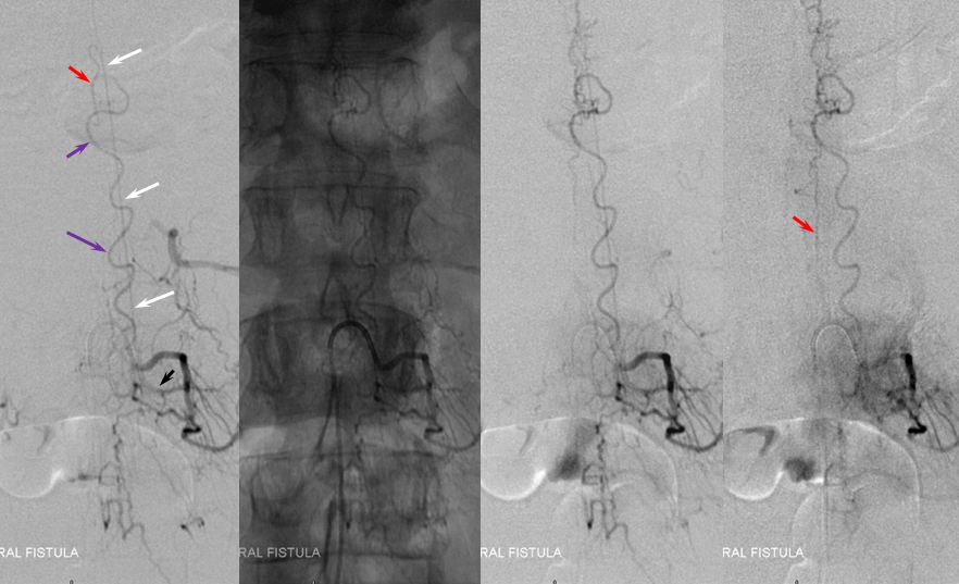
The next task is to find regional radiculomedullary contributors to the anterior spinal axis — the radiculomedullary arteries. Typically, injection of the radiculomedullary artery of the lumbar enlargement (Adamkiewicz) should lead to visualization, in 4-8 seconds, of regional spinal surface and draining veins. Failure to see these veins is strong indirect evidence of underlying venous congestion, which means that the fistula or another cause of congestion must be searched for and found. In this case, we found the fistula first, but a knowledgeable angiographer will continue with the diagnostic portion until the ASA (bright green arrows) is found, in this case at the left L1 level; the Adamkiewicz is marked by dark green arrows. Notice that venous phase image (to the right) has no spinal veins, confirming venous congestion.

Video of the same:
Now that we have this diagnostic information, the entire case can be fully understood. In this rather fortunate patient, a relatively high-flow (for dural fistulas) fistula has taken over a large length of cord venous drainage. Fortunately, existence of caudal right L5 drainage kept the patient from being severely symptomatic. Because the cord is unable to use the venous system draining the fistula, it is forced to find alternative pathways, which are severely insufficient, given the extent of cord edema on MRI. Appreciating the kind of diagnostic information available by combination of MRI and angiographic studies allows one to understand why patients with dural fistulas progress in stepwise fashion, ultimately entering a relatively quick downward spiral. Should the right L5 outlet close, the already marginal cord drainage would be subjected to sudden and massive competition from the fistula, which would in this case precipitate acute and likely severe clinical decline.
For treatment, a microcatheter (tip marked by black arrow) is navigated into the radicular artery (red) supplying the fistula as far as possible to achieve a “wedged” position — meaning that the catheter can not be advanced further, allowing for better control of the subsequent nBCA injection. Large white arrow marks the site of fistula. Also present is another dural artery supplying the fistula from below (orange arrow), transiently opacified by reflux.

This is a somewhat unusual fistula. Most spinal dural fistulas are located in the nerve root sleeve, at the level of the radicular artery. In this case the fistula is lower, and furthermore has an unusual additional feeder from below. The appearance of these two feeders is reminiscent of the ventral epidural venous plexus. Could this be an epidural fistula? Possibly, however in those rare cases there is usually an epidural venous pouch present (see Spinal Epidural Fistula page) which we did not see here. We subsequently obtained a CT of the glue material to see if part of the glue was epidural, but it did not seem to be the case.
Video of the same microcatheter injection:
Again, video of distal fistula drainage better seen through microcatheter injection:
Next comes the glue shot, using 40% nBCA and 60% oil, with no tantalum. In retrospect we could have used less oil, so as to let the glue polymerize quicker. On the other hand, using too much glue risks polymerization before reaching the fistula point, which would require the patient to go to surgery to definitively close the fistula, unless another glue shot position can be found. So we erred on the side of making sure to first and foremost reach the fistula. However, having knowledge of the feeder from below we anticipated that once glue reaches the fistula, it will be quickly taken up by the inferior feeder into the vein. The problem here is that we wish to preserve these spinal surface veins, which we hope the cord will use once the fistula is closed. Closing these veins in fact is detrimental — as proven by the early surgical experience where these veins were stripped off the cord before the true pathophysiology of the fistula was understood (see Spinal Dural Fistula page). If you watch the glue shot video carefully, this is exactly what happens, as the first component of the glue to reach the fistula flies quickly up into the vein, where it fortunately solidifies. The answer to seeing this kind of fly-thru behavior is to counter-intuitively push MORE glue faster, so that the shunt will be closed quickly, which is what was done here. The final result is durable glue deposition across the fistula.
Could Onyx be used in this circumstance to minimize the chance of glue fly-thru into the surface veins? I think yes, by those with sufficient spinal Onyx experience. We use nBCA in almost all spinal embolizations, as do most practitioners of spine work.
Post-embolization check requires injection of contralateral, and isilateral superior and inferior adjacent segmental arteries to confirm lack of collateral fistula reconstitution (in this case, right T10, and left T9 and T11 segmental arteries, not shown).
Next comes anterior spinal injection — in which we now hope to see veins in the venous phase, to confirm successful resolution of venous congestion. In fact, we do see these veins (bright blue arrows). Furthermore, notice how the venous loop previously opacified via injection of the fistula (brown arrow, rightmost picture with bright blue border) is now seen in the venous phase of the anterior spinal artery injections (bright blue arrows). Isn’t that elegant?! Spinal vascular art at work! The injection confirms that spinal cord can now use the only remaining competent large vein previously parasitized by the fistula.

Video of the same:
We obtained a CT scan of the thoracic spine to see where the flying glue ended up — actually it was rather distal for our liking. Reconstructed coronal images are best for this, since they correspond with angiographic projections. The same structures can be seen in the glue cast of CT scan and microcatheter injections — radicular artery (pink), fistula point slightly below the nerve root sleeve (blue), a small surface vein seen during angiography on some images (white) and, most notably, a rather distal loop of posterior spinal surface vein (a.k.a. extrinsic venous system) marked by the yellow arrow.

So, the first portion of the glue that was taken up by the inferior feeder has dislodged from the main glue column and traveled rather far — over the apex and down, finally polymerising at the level of T11 pedicle. Once this happened, the flow proximal to this point was reduced, allowing for the glue column to polymerise at the level of the fistula. Despite glue occlusion of the upper aspect of this principal draining vein, the cord continues to use the same venous system inferiorly, as evidenced by opacification of the main draining radicular vein following post-embolization ASA injection (above). Still an excellent result.
The patient was kept on heparin drip for 2 days to minimize possibility of propagative post-embolization venous thrombosis, particularly in the surface vein with glue cast, and will be discharged on a baby aspirin for at least a few weeks.