
Pipeline Embolization Device and Treatment of Brain Aneurysms

PURPOSE
This page is intended as a comprehensive guide for use of both Pipeline Flex and Pipeline Classic Embolization Devices, covering various aspects of device selection and deployment. Best results are always achieved through thorough knowledge of the tool with which one is entrusted, combined with a healthy and honest respect for the intrinsic limitations of the device and the operator. This page constitutes the most comprehensive guide for use of a neurointerventional device in history of the field. It is dedicated to my mentors, Dr. Peter Kim Nelson and Dr. Tibor Becske, to whom all credit for this work rightly belongs, and to all our Pipeline patients, without whose trust none of this would be possible.
CONTENTS
SECTION 1
Addressing Landing Zone Diameter Mismatch
SECTION 2
Pipeline Classic Deployment Guide
Pipeline Flex Deployment Guide
Introduction
The Pipeline, a.k.a. Pipeline Embolization Device, a.k.a. PED, is a member of larger family of endovascular tools designed for treatment of cerebral aneurysms. The devices have collectively come to be known as “flow diverters”, though the term itself is misleading, as aneurysm cure is not achieved by that mechanism. All flow diverters are, essentially, high metal coverage (low porosity) stents, which are deployed across the aneurysmal segment, singly or in a telescoping fashion. Successful placement of such device or devices ideally produces immediate changes in regional circulation, redirecting blood flow past the aneurysm into the distal, normal artery. The resultant intra-aneurysmal stasis promotes thrombosis within the aneurysm, which leads to an angiographic appearance of “cure.” Actual cure is not achieved until subsequent “endothelialization” of the stent, whereby the vessel intima overgrows the device, definitively excluding the aneurysm from parent circulation, and usually followed by aneurysm involution. Symptoms of mass effect may improve or resolve at this stage. Flow diverters are primary endoluminal devices, designed to address the deficiency in arterial wall which represents the root cause of aneurysm formation by repair of that defective segment, rather than endosaccular tools such as coils, which target the aneurysm rather than the underlying parent artery defect, with the latter frequently continuing to manifest itself as post-treatment recurrence. An article by Fiorella, Lylyk, Szikora, Kelly, Albuquerque, McDougall, and Nelson, illustrating the above concepts, is part of essential reading for Pipeline operators.
Flow diversion concepts have been in development for some time (about 20 years), however the various materials (alloys, practical delivery systems) have somewhat lagged behind conceptual thought. The first generation of efficacious and certainly imperfect devices have come into use between 2005-2010. The Pipeline was approved in US by the FDA in April of 2011, as a result of the most comprehensive safety and efficacy trial (PUFS) in neurointerventional history (link to FDA Safety and Efficacy data here).
A combination of geometric, materials science, and manufacturing factors have resulted in all flow diverters sharing a number of common features. All are so-called “braided stents” — a series of very thin wires weaved like braids into a stent-like construct. The resulting product can be stretched into a diameter small enough to fit into a practical delivery catheter. The device is therefore packaged in an elongated form, and foreshortens as it opens during deployment. This is in contrast to “laser-cut” stents (such as the Neuroform), which largely maintain their length during deployment, being compressed rather than stretched to fit into the delivery catheter, and therefore having intrinsically lower degree of “metal coverage”.
Device and its Properties
The Pipeline is a braided stent, composed of 48 wire strands woven together on a braiding machine which controls device diameter and pitch (angle between wires). There are no links or other physical connections between individual wires. The device ends are created by cutting, with no markers or other modifications. The bulk of device is made of a relatively radiolucent Cobalt-Chromium alloy, with every 4th strand made of radio-opaque Platinum-Tungsten. Each strand is ~30 microns in diameter, with no reported size difference between Co-Cr and Pt-W strands. The device diameter ranges from 2.5-5.0 mm in 0.25 mm increments, with lengths from 10 to 35 mm. All devices are designed to open approximately 0.25 mm beyond their nominal diameter, such that the largest presently available diameter would be around 5.25 mm.
Two delivery systems of the Pipeline are presently available — Pipeline Classic and Pipeline Flex. The device is identical, however the delivery systems and, hence, the delivery itself, are quite different. Below is a brief description of the two systems. Detailed review of delivery strategies is found further down.
Pipeline Classic
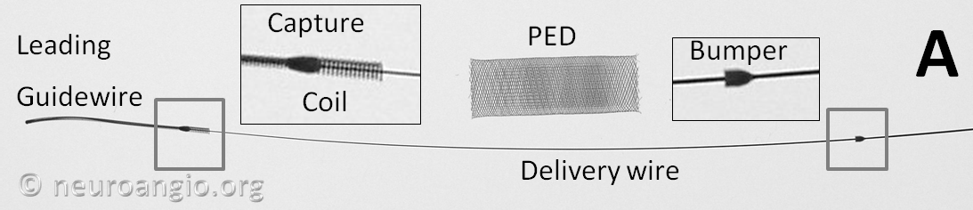
The device is mounted on a delivery wire, which consists of a 15 mm long Platinum leading guidewire that transitions into a capture coil, under which the forward (distal) end of the device is contained. The device diameter is reduced by elongation, which allows it to be inserted into a protective delivery sheath; as a result, the packaged device is substantially (2-2.5 x) longer than its nominal length. At the back (proximal) end of the device, a bumper (pusher) is mounted onto a delivery wire, which pushes the device forward during deployment.
Pipeline Flex
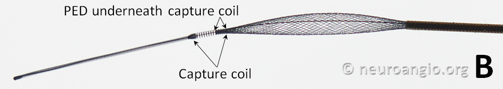
The Flex delivery system dispenses with the Capture Coil. Instead, the distal edge of the Pipeline device is protected during its advancement through the delivery microcatheter by two polytetrafluoroethylene (PTFE) sleeves, which measure approximately 2-3 mm in length (usually closer to 3). The device is mounted by elongation, and foreshortens during delivery, just like Pipeline Classic and all other braided devices. On the proximal end, a resheathing pad, about 3 mm in length, is placed between two markers — the resheathing marker and proximal delivery marker. The device is mounted over the resheathing pad, between the pad and the protective sheath when packaged, and subsequently between the pad and the delivery microcatheter. Friction between the resheathing pad, the Pipeline device, and the delivery catheter allow for the device to be retracted and re-deployed. Thus, it is critical that only 027 size microcatheters be used for delivery — the Marksman is currently the microcatheter of choice, with its internal diameter and coating (affecting friction) evaluated for use with the Flex.

Device Porosity
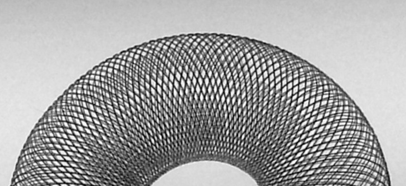
Although nominal metal coverage (reverse of porosity) of the device is listed as 30-35%, in practice the porosity changes substantially depending on device configuration and diameter size relative to the artery into which it is placed. When seen under magnification, the ultrastructure of the device consists of a lattice of wires, forming interstices which look like rhombi. The nominal angle between the strands for the unconstrained (fully opened) device is set during manufacture. The porosity of the device is determined by the area of the individual cell (pore) relative to that of braids. The braids are ~30 micrometers in diameter.
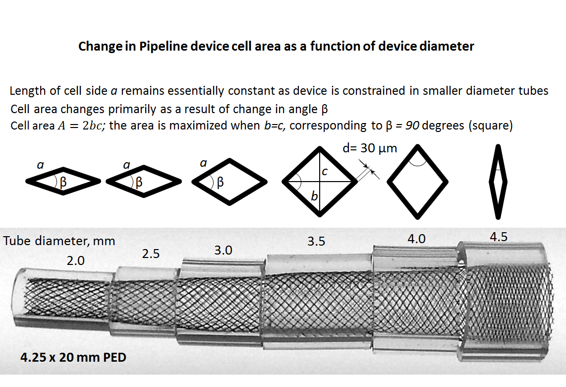
The side length a and angle of the rhombus beta vary depending on relative sizes of the device and its recipient artery, and in some circumstances the degree of compression. The area of the rhombus is proportional to porosity and is determined as A=b*c/2, where b and c are rhombus diagonals. When the Pipeline is allowed to open fully, the beta angle of the rhombus is about 60 degrees. When the Pipeline is placed in a vessel with a diameter smaller than the nominal size of the Pipeline device, beta increases until it reaches a maximum of 90 degrees, at which point the rhombus becomes a square, corresponding to state of maximum porosity. This relationship holds true because, unlike beta, the length a of each individual cell does not change substantially in a straight segment. With even more oversizing, the square becomes a rhombus again, however in a different orientation, and porosity again falls. Therefore, the function of porosity vs. diameter of the device looks like a parabola.
The image above illustrates this concept by placing a 4.5 mm device into progressively smaller clear tubes. Notice that highest coverage is achieved at full expansion of 4.5 mm, whereas at 3.0-3.5 mm the coverage is near minimum, corresponding to the “square” orientation of the filaments. Beyond that, coverage again increases, though it is unlikely that a 4.25 mm would be deployed in vessels of this size. Therefore, for practical purposes, oversizing implies decreased metal coverage (increasing porosity). This is also illustrated in the graph below, for the same 4.25 mm device. Cell area is inversely proportional to “coverage”
Below is a comprehensive graph of % metal coverage vs. device diameter for 4 devices of different nominal diameter.
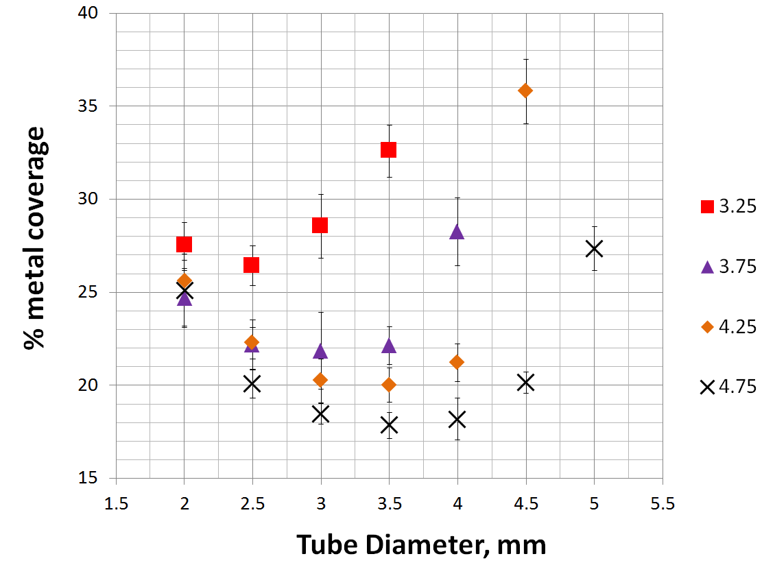
As you can see, the degree of metal coverage falls quickly when the device is oversized relative to the parent artery. In fact, so quickly does coverage fall that oversizing by as little as 1 mm has the effect or reducing coverage from roughly 30% to about 20%. This continues for the next 1 mm of oversizing. For example, placing a 4.5 mm Pipeline into a 3.5 mm artery will result in metal coverage of about 20%, and this low coverage will be true for vessels between 2.5 and 3.5 mm. Only in vessels smaller than 2.5 mm will coverage begin to rise again, however it is not likely that such dramatic oversizing will be seen often.
The simple meaning of this relationship is that, practically speaking, the % metal coverage of any SINGLE device is unlikely to be 30%; true values will be around 20% for larger diameter devices, and in high 20’s for smaller devices such as a 3.25 mm one. The obvious implication is that most cases, and particularly large and giant aneurysms for which device was approved, are likely to require more than one device to achieve the degree efficacy expected based on PUFS data. Opinions on this matter differ among users; it is hoped that those entertaining the opposite notion will bring to the debate the same quality of in vivo and in vitro data as presented herein to support the contrary opinion.
Consequences of oversizing
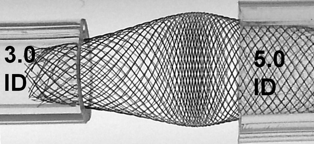
While oversizing may be seen as an advantage if the landing zone contains functional perforators, on balance it is quite deleterious. Firstly, oversizing decreases metal coverage (increases porosity), reducing both extent of flow diversion and efficacy of endothelialization. Secondly, when an oversized device opens to its nominal size within the fusiform aneurysmal segment, a transition zone (TZ) of decreased porosity is created between the constrained device in the artery and its fully opened state, as seen in picture below. It is hard to imagine how this configuration would promote endothelialization and flow diversion. This is illustrated in the diagram below, where a “transition zone” forms due to distal constraint of the device in a substantially smaller diameter vessel.
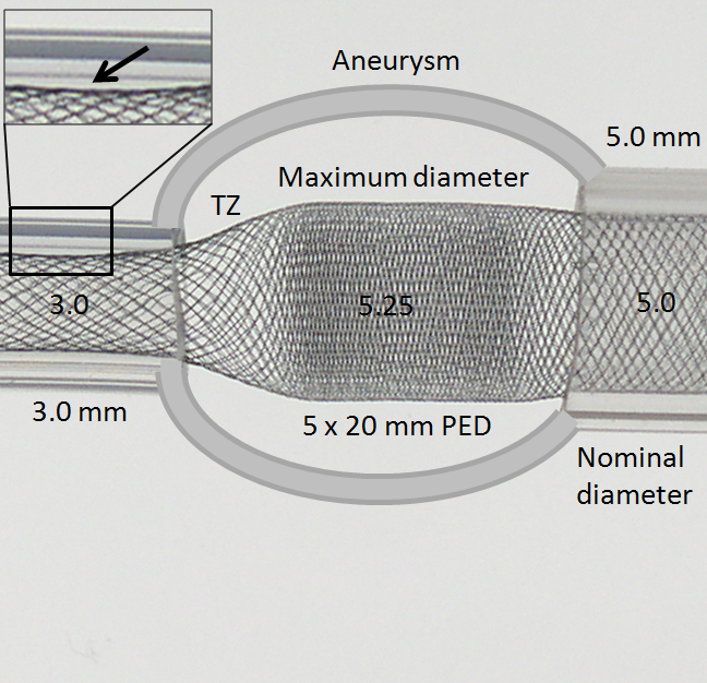
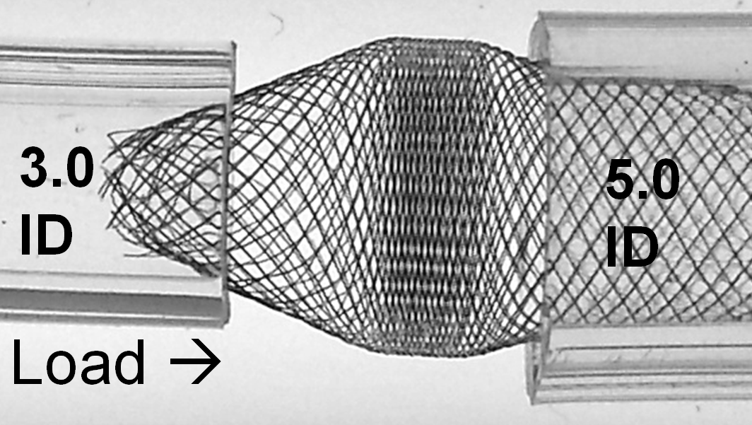
Many important points are visible here. The transition zone (TZ) of reduced coverage cannot be changed by forcing the PED further into the aneurysm, as seen in picture below. In fact, only the fully opened part of the device can be “packed”. The porosity of device already placed into an artery cannot be changed by attempting to push more device into the vessel. Likewise, the Transition Zone will not collapse with pushing. In fact, “loading” under these circumstances may be deleterious as it may create preferentially less resistance to inflow (which is often directed into the distal wall) than outflow (which often takes place at the proximal end of the aneurysm), thereby increasing intra-aneurysmal pressures.
Notice also how the device does not fully appose the “wall” at 3.0 mm due to its “shape memory” (black arrow, inset above). This means that the device will have a tendency to “watermelon-seed” itself into the aneurysm if the distal landing zone is short, which is another disadvantage of oversizing, and may lead to eventual “migration” of the distal end fully into the aneurysm. This is not device malfunction — it is an appropriate device response to its deployment position, much like continued patency of an aneurysm which was clipped over a calcified neck is hardly a case of clip malfunction.
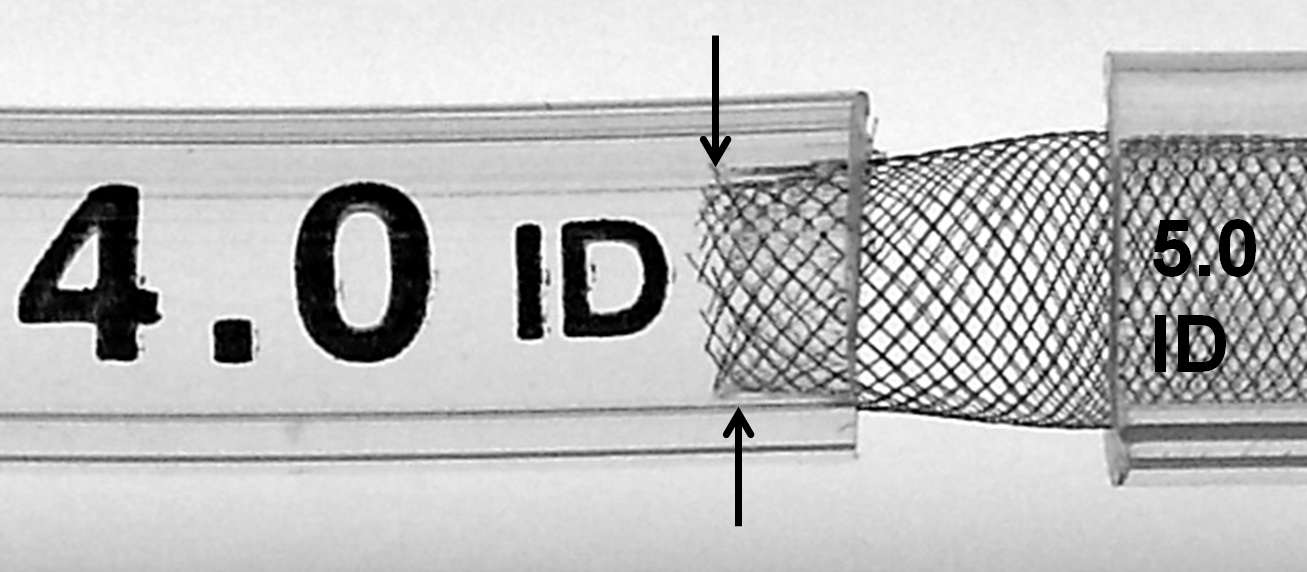
Even a relatively modest degree of oversizing creates memory shape effects which must be taken into account. In the following illustration, a 5.0 mm device is deployed within 4.0 mm and 5.0 mm tubes — a relatively common mismatch. Notice how the memory shape effect (which was illustrated above in a relatively long landing zone) is unopposed by the shorter landing zone here (arrows).
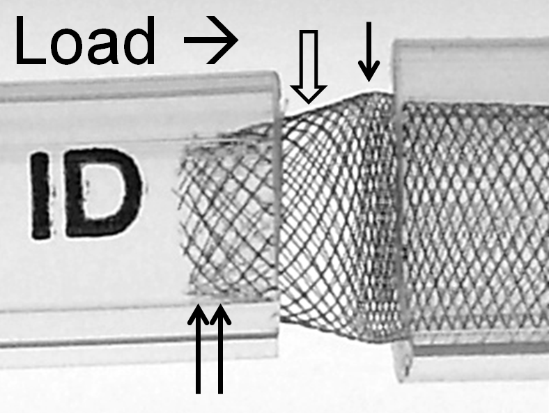
While it might seem like a good idea to “reinforce” this short landing zone by “packing” the device, this maneuver can in fact exacerbate the issue by counteracting the intrinsic radial force of the device — increasing long axis load in setting of constraint generates a centripetal force vector which acts to further approximate the ends of the device and increase the degree of fishmouthing (double arrows), as illustrated below.
The above effect is, not unexpectedly, magnified with increasing degree of mismatch, which is illustrated below; notice the severely reduced “coverage” of the transition zone and obvious “fishmouth” configuration at the 3.0 ID end.
With loading (packing) the device, it really starts to look quite treacherous. It is easy to see that no kind of manipulation (balloon, wire, etc) will be able to adequately open up the 3.0 ID end of the device. Can one fault the device for obeying the laws of geometry and physics?
The solution to the problem, if you must needs oversize so grossly, is to make sure there is a generous landing zone of the constrained end. It may still be possible, in the above example, to telescope another device into the 3.0 ID “vessel” and deploy it with a large enough landing zone to tack the fishmouth down to the inner wall.
Addressing proximal and distal landing zone diameter mismatch
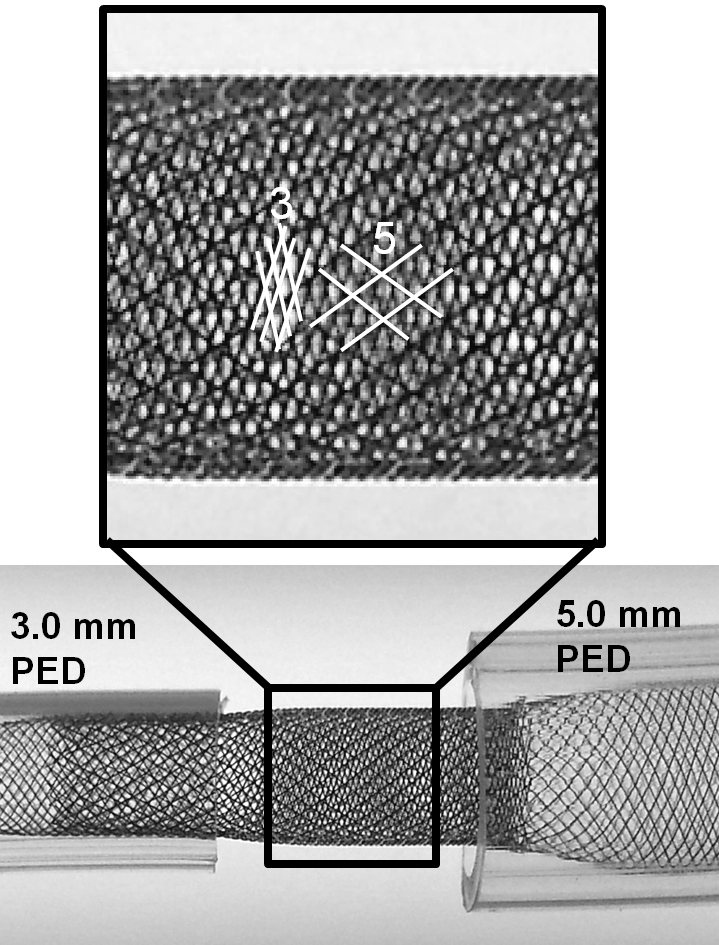
There are only two solutions — devices with different size ends (which do not yet exist on the market, and which would be tricky to manufacture) or using multiple devices. The second solution is most practical — each landing zone receives its appropriately-sized device, which are then telescoped into each other, thus minimizing transition zone effects, while increasing overall metal coverage for the overlap segment. Larger vessel mismatches may require yet more devices for optimal coverage of all transition zones. In the example below, a 3.0 mm device is chosen for the 3.0 mm “distal” vessel, and deployed across the aneurysm so as to free-float in the 5.0 mm “proximal” vessel.
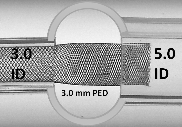
A 5.0 mm device is then telescoped sufficiently into the 3.0 mm device, to double-cover the entire neck and to shift the transition zone into the proximal vessel. The extent of “distal” double-coverage can be easily varied based on perforator or other considerations.
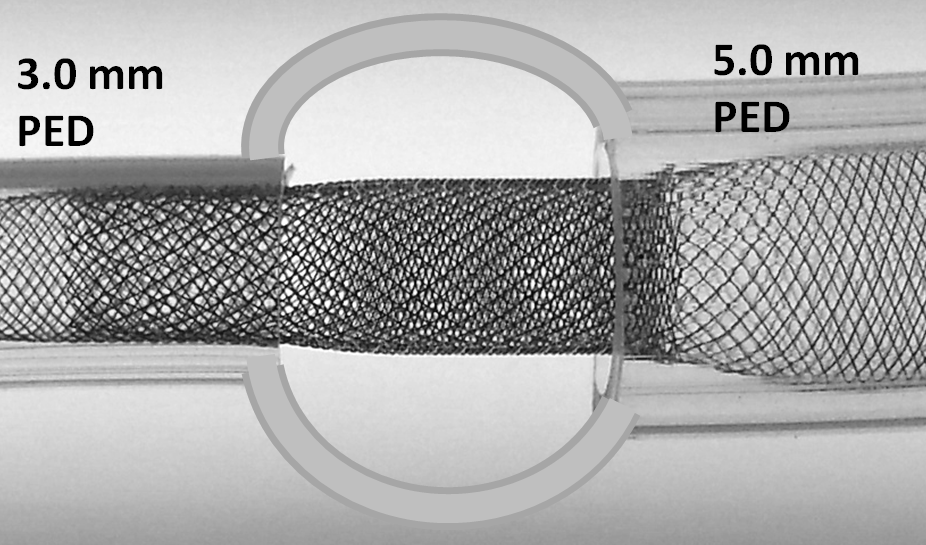
Notice how one can appreciate the distinct overlapping patterns of the 5.0 mm and 3.0 mm devices within each other, with a low coverage pattern of the constrained 5 superimposed on the nominal pitch of high coverage 3 device.
Below is an illustration of loading pressure applied to the device in setting of size mismatch, with no collapse of the transition zone, yet another disadvantage of oversizing. Notice also that application of forward packing force does not change porosity of device already deployed in the artery. Only porosity of the freely expanded device (that located in a fusiform aneurysmal section or in a vessel larger in size than the maximal device diameter) can be changed by loading, pushing, packing, or whatever else it may be called.
![]()
In summary, it is difficult to over-emphasize the importance of appropriate sizing, particularly manifested in the twin temptations to oversize and minimize the number of devices.
Porosity Along Curvatures
Seeing how many considerations arise from even “simple” use of the PED in an idealized straight vessel segment (discussion above), now imagine how much more complex things really get when curvature is added to the equation. In practice, however, curvature is the more common scenario. Obviously, device porosity changes along curvature. The exact changes are nearly impossible to predict in real-life situations — there are simply too many variables — device size, artery size, change in artery size along curvature, degree and length of curvature, etc. Broadly speaking, one can define an inner and outer curve of a device which is placed along a curve. For any such device, the extent of coverage is minimal at the outer curvature, and maximal at the inner curvature. However, unlike the scenario with oversizing, the extent of metal coverage is now determined by both changes in cell angle beta and cell side length a. This happens because for the device to accommodate to a curve without “ovalization” the filaments must slide substantially relative to each other, which means that on the outer curve the rhombus side length is increased a lot (proportional to degree of curve) whereas at the inner curvature the side lengths are substantially reduced. This is well appreciated in the following picture.
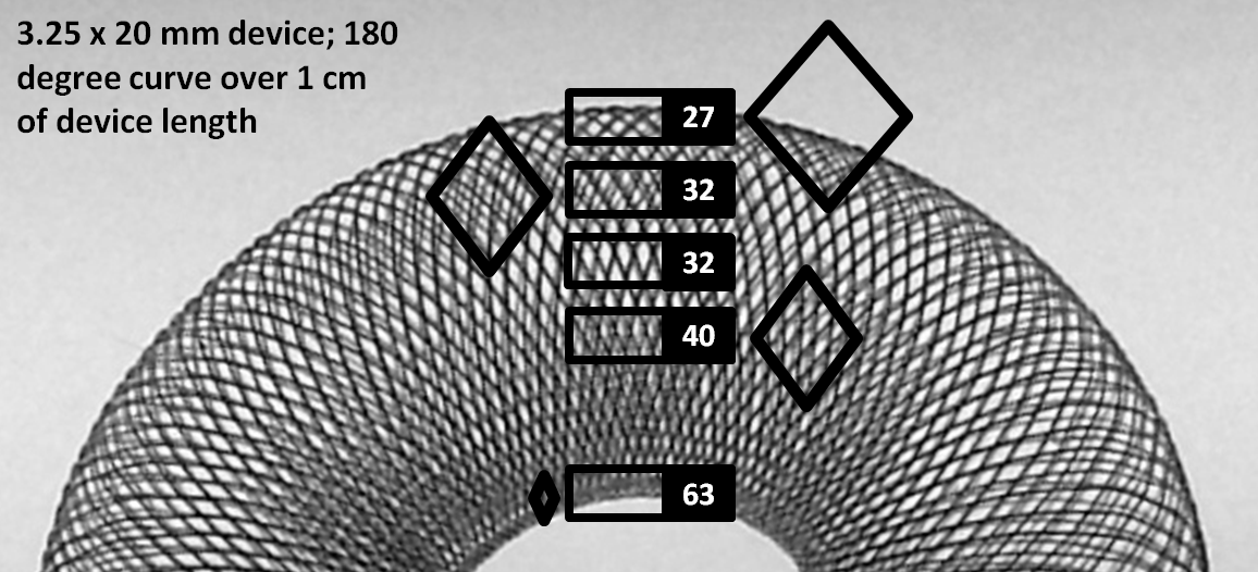
As you can see, porosity changes dramatically along curvatures, particularly at the “inner” curve, where metal coverage values can be very high, while at the outer curve these values are relatively lower, though not as low as for oversized devices. The reason coverage continues to be reasonable even on the outer curve is because this device happens to be maximally expanded, and not constrained within a tube. It so happens that a device, when simply laid out on a table or fully expanded in the body, has coverage values of between 40-50% — substantially higher than the ~30% advertized value. Nevertheless, these observations have important implications for treatment of aneurysms located on curves. Aneurysms with necks or inflow zones located at the outer curve (usual situation) receive less metal coverage and are subjected to inflow jets from the parent vessel. This is especially true when the device is not freely expanded along a curve, but rather oversized. It is especially important to make sure that these aneurysms are treated with optimal metal coverage — what “optimal” means remains to be determined, however in our practice the implication is usage of multiple devices. On the inner curve however the infrequent aneurysm neck would be quite well covered even with a single device.
From all of the above, it should be clear that real-life coverage in the range of ~30% along the whole treatment segment is going to be essentially impossible with a single device. There are many reasons to use multiple devices, some of which are apparent from the aforementioned discussion of coverage and oversizing alone, while others concern issues of overall construct stability in treating large fusiform aneurysms, and strategic considerations of building long constructs. What is the strategy for overlapping devices in therms of coverage?
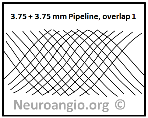
This question can be answered by imagining what might be the consequences of deploying two devices of identical nominal diameter within each other. For example, a 3.75mm device is telescoped into an already placed 3.75 mm device. What happens to coverage depends on the allingment of the device braids relative to each other. One can imagine a scenario where the two device braids perfectly overlap — in which case this kind of double-coverage actually produces no or almost no net increase in actual coverage! — as seen in the following picture.
On the other hand, a perfect half-phase separation of braids will almost double coverage, like this:
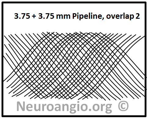
In practice, given the many local variations in vessel diameter, device load, etc. the actual coverage will vary along a continuum between these two extremes:
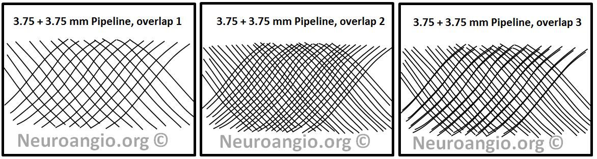
From this simple consideration, it can be concluded that using two identical diameter devices for multi-device constructs is a bad idea as far as coverage is concerned. Another conclusion, and an equally important one, is that multicoverage does not simply produce a new coverage number — rather, it yields a RANGE of coverage values. This range is widest when identical diameter devices are chosen, and it becomes progressively tighter when devices of increasingly different diameters are selected.
For example, if one where to place a 4.25 mm diameter device into a 3.75 mm one (instead of another 3.75 mm like we saw above), then the pitch of the two devices will be different and therefore the range of coverage values narrower. The greater the difference in nominal diameters, the smaller the range, and therefore the more uniform coverage. Of course, the actual coverage number will be in between the two extremes of using identical diameter devices, but uniformity is much more important, as seen in the example below:
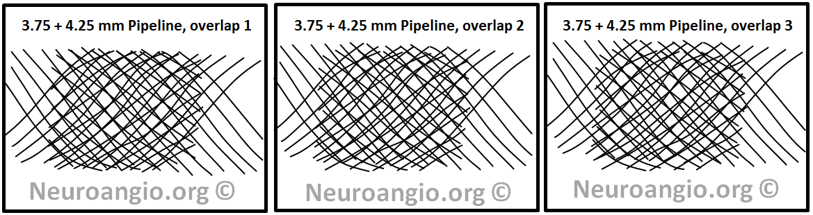
As you can see, no matter what pattern of overlap is chosen, the coverage is more uniform. This can be seen in another example below.
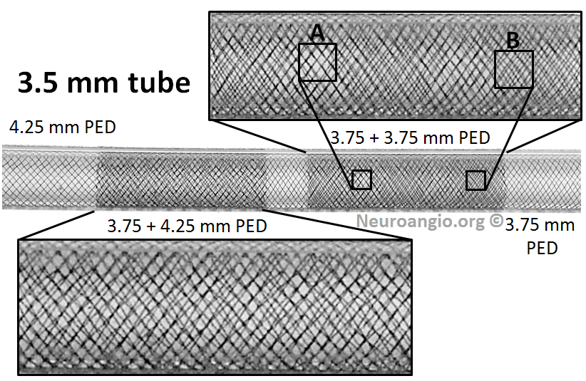
Notice how overlapping two 3.75 mm devices results in patches of near-zero coverage gain (A) and substantial gain (B). This variation, I believe, is detrimental, and it is not seen in the 3.75 mm + 4.25 mm device overlap.
What actual coverage values to expect? Here is some data, for select tube and device pair combinations:
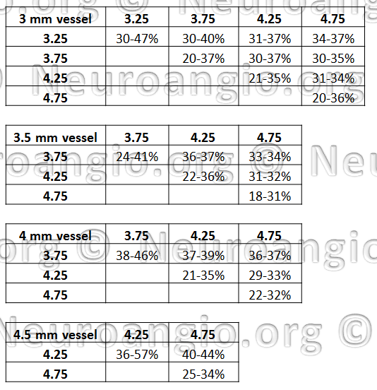
There is a wealth of information here. Perhaps one of the most important conclusions from this table is that, again, coverage values in the range of 30% are almost never achievable with single device use. However, if one were to use two different diameter devices, then 30% and higher values can actually be very reasonably expected.
Whatever other considerations may be, the bottom line is that for purposes of actual treatment success, just like a Neuroform or an Enterprise is more effective than nothing, and a Pipeline is more effective than a Neuroform or an Enterprise, so are two Pipelines going to more effective than one. Where the diminishing marginal returns curve becomes flat enough is not going to be answered for each case in each instance. However, it is sure not going to be at 20% coverage, but that will take some time to be generally recognized.
Summary of Device Properties
Successful use of Pipeline (and all flow diversion devices) requires appreciation of geometric device properties, particularly as they relate to changes in porosity. The following points are emphasized:
* device should be sized as close as possible to recipient artery. This requires careful measurements, which take time and patience
* significant mismatch in diameter between proximal and distal landing zones should be considered as requiring use of multiple devices, each appropriately sized to its intended landing zone
* in practical situations, device metal coverage is likely to be significantly lower than nominal ~30% value
* the preponderance of in vitro and in vivo evidence supports use of multiple devices to achieve optimal neck coverage in most situations, and particularly along curvatures
All images, graphs, and values above are results of experiments and observations carried out in our lab. This particular data is hereby made freely available to the community, with implicit permission for reproduction, provided that www.neuroangio.org is explicitly referenced as the original source.
PLEASE NOTE THAT THE ABOVE RELATIONSHIPS BETWEEN DEVICE-ARTERY SIZE, CURVATURE, AND METAL COVERAGE ARE ONLY APPLICABLE TO THE PIPELINE. OTHER FLOW DIVERTERS HAVE DIFFERENT PROPERTIES. In particular, it seems to me that the Silk device behaves differently, as it seems to be designed with minimum coverage at the nominal size, where its rhombus angle is close to 90 degrees. Oversizing Silk may actually increase coverage, according to my interpretation of one excellent study by Aurboonyawat, Moret and colleagues . I have not had the opportunity to conduct the above experiments for Silk, again emphasizing the point that none of the above Pipeline observations should be extended a priori to other flow diverters, although some of which do appear to me to behave similar to the Pipeline — at least according to another series of excellent experiments by Makoyeva, Raymond and colleagues.
DEPLOYMENT
The following second portion addresses various aspects of Pipeline Classic and Pipeline Flex deployment in separate comprehensive sections
Pipeline Classic Deployment Guide
Pipeline Flex Deployment Guide
POST-PROCEDURE CONSIDERATIONS
Anti-platelet management: We have not had a single in-stent thrombosis in the anterior circulation after we began to routinely measure P2Y12. Further discussion is outside the scope of this page.
Follow-up in our group is same as in PUFS — a 6 month angio, unless clinical considerations merit an earlier study. The next follow-up is a 12 month catheter angio. We prefer 3 and 5 year catheter angiograms to CTA. We learn much more about reasons for the occasional incomplete occlusion by doing catheter angio than via any other modality.
In the opinion of the author, cross-sectional follow up is essential, particularly in large and giant aneurysms. Angiographic “cure” without actual cure by endothelialization-driven exclusion of the aneurysm from parent circulation is by now a well-known phenomenon. This scenario is especially true in the one-and-done setting which, as a principle, this group does not support.
Mass effect symptoms respond variably, depending on nature, severity, and duration of symptoms. Not infrequently the symptoms worsen before they get better — likely acute intra-aneurysmal thrombosis and inflammation, followed by aneurysm collapse. Cross-sectional, in addition to catheter angiographic followup of all patients with mass effect symptoms is essential. Aneurysm enlargement in the face of apparent angiographic cure is lack of endothelialization — and nothing else. These cases need more stents — and more than a few — before its too late.
Pain is the rule in certain locations — cavernous especially, followed by posterior fossa. Likely due to aneurysm thrombosis, it usually develops in subacute fashion, and is usually good rather than bad news. A short course of steroids works great, in addition to other meds. Pain typically lasts from a few weeks to several months. However, if pain develops or recurs after some time of pain-free interval, say several months, this is reason for prompt imaging, including cross-sectional, to evaluate for possible growth of aneurysm sac, even if angiographically the aneurysm seems “closed”.
Follow-up angiography — persistence of aneurysm
Our rate of 6 and 12 month non-occlusion remains identical to PUFS, as is our average stent number per case. Those using less devices will find less cures. We will routinely obtain cross-sectional imaging for patients with angiographic “cure”, as above.
When an artery emerges from the aneurysm (neck or dome) such as the ophthalmic, one of two things is likely to happen: either the ophthalmic will stay open, together with the aneurysm, or both will go down. The artery usually closes slowly (like an endovascular Silverstone clamp) and the external carotid takes over with no issues: about 20% of our ophthalmic arteries go down on follow-up, with one case of amaurosis and no cases of any vision loss, partial or complete — including PUFS cases with dedicated perimetery testing. In the posterior circulation, the situation is more difficult, as all arteries are eloquent. In any case, if you feel that the aneurysm is kept open by an artery arising from the aneurysm, a judgment call is required.
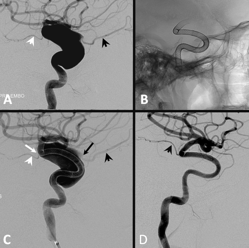
Below is an illustration of exactly such differences in a patient with a huge fusiform trans-segmental aneurysm (A). The ophthalmic (black arrowhead) arises from the “dome”, while the anterior choroidal (white arrowhead) is situated on the tapering segment of the “fusiformity”. Both are multi-covered by the Pipeline construct. The ophthalmic ostium is away from the device (black arrow), while the ostium of the choroidal is purposefully situated immediately adjacent to the construct (white arrow). Eight months later (D), the ophthalmic is closed (asymptomatic, ECA reconstitution), while the choroidal continues to fill.
Occasionally collateral reconstitution can be seen in other scenarios, for example in this patient with a giant MCA bifurcation aneurysm, with a small inferior division coming from the neck. Two PEDs produced tremendous flow diversion, with immediate non-visualization of the temporal lobe. Injection of the vertebral artery shows robust collateral reconstitution of the inferior division all the way to the ostium. Case courtesy of Dr. Howard A. Riina
Conclusion
Though a number of initial issues with Pipeline Classic delivery system have been addressed in the Flex, the device remains challenging to deploy. Mastering it requires patience and humility, at all levels of expertise. A concept of strategy, in terms of device size, number, and placement, emerges with experience and is essential to maximizing efficacy.
Acknowledgements
Everything I learned about Pipeline can be traced to the influence of two great teachers– Dr. Peter Kim Nelson and Dr. Tibor Becske. Whatever contributions I made have been influenced by their vision. This page would never come about without the support of our former fellows Eytan Raz, Daniel Zumofen, Mattew B. Potts and Erez Nossek. For the purposes of disclaimer, views and opinions expressed on this page are entirely my own.
Disclaimer
I, Maksim Shapiro, am a Pipeline proctor and per diem consultant with Covidien, the manufacturer of Pipeline. No financial or other support whatsoever was provided by any legal entity, group, or individual towards creation of this page, or www.neuroangio.org as a whole. Pipeline devices featured in ex-vivo images above were donated by Covidien for general training purposes, and related projects. The clear plastic tubes of pre-defined diameters are Endotracheal Tubes, generously donated by the blue anesthesia cart, second and third drawers from the top. I have no other conflicts of interest to declare. See Disclaimer section for general disclaimer information.
Questions, Comments, Inquiries
May be submitted via the Contact Us section or by calling the office at 1-212-263-6008