Development — this abbreviated, important section precedes discussion of adult anatomy. A more complete discussion is found in the dedicated section of neurovascular embryology.
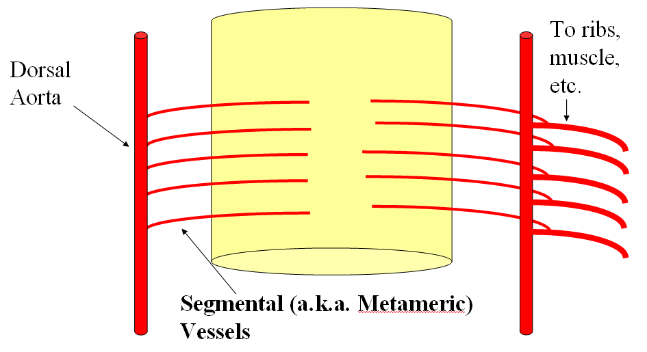
The basic arrangement of the spinal system consists of a metameric grid of trasversely oriented segmental vessels, connected by various longitudinal channels. This simple bit of knowledge goes a long way in understanding spinal anatomy. Millions of years of speciation have taken place upon a basic building block of the organism — the metameric segment. Just like the fly and the worm, the human body consists of metameric segments, with ecto-, meso-, and endodermal elements. Each vertebral body, its ribs, muscle, nerves, and dermatome, correspond to one level or segment. It is perhaps easiest to appreciate this concept at the thoracic level, where each rib, vertebral body, and other elements constitute the prototyical segment. In the early human embryo, the neural tube is first supplied by simple diffusion. When its limits are reached (200 micrometers perhaps), a primitive vascular system consisting of paired dorsal and ventral aortae (longitudinal vessels) and transversely oriented segmental arteries come into play to vascularize the developing tissue of the embryo.
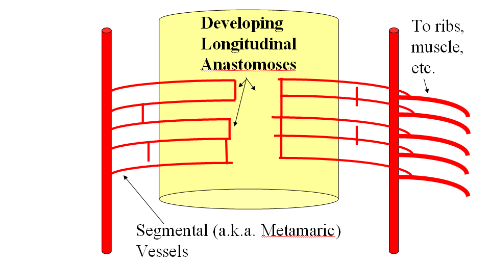
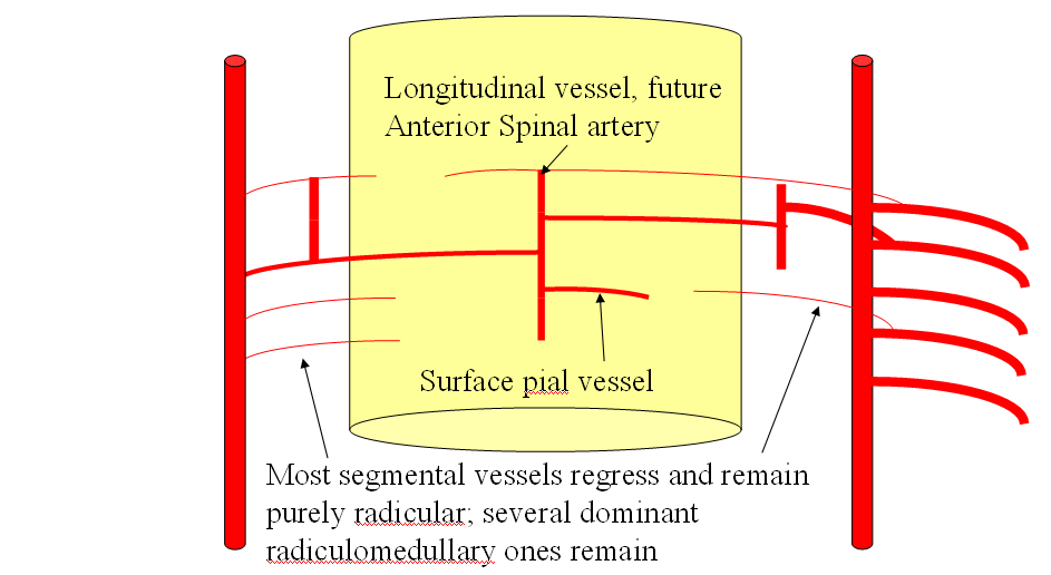
As the tissue of spinal cord continues to enlarge, new longitudinal connections form between the transverse segmental arteries, most likely to facilitate distribution of blood within the vascular system. This pattern is seen throughout the body, but is somewhat easier to recognize in the vertebrospinal arterial system, where it gives rise to adult anterior spinal artery and numerous extradural longitudinal segmental connections which will be discussed below.
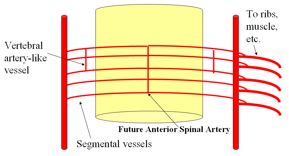
Gradual establishment of dominant longitudinal vessels leads to regression of most transverse segmental arteries, except at some levels where such vessels persist in supplying the longitudinal artery.
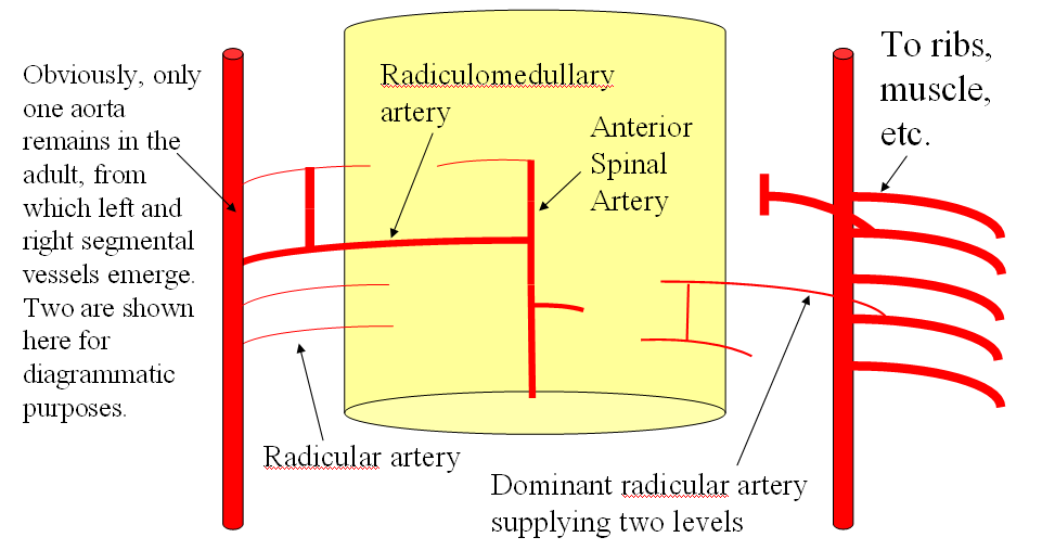
This process, in terms of the spinal cord, gives rise to the familiar adult appearance of the anterior spinal artery and its remaining radiculomedullary feeders, while most segmental arteries previously connected to it in early fetal life are limited to supply of the nerve root and adjacent tissues in the adult.
The same pattern of development takes place in the extra-axial, paravertebral space, where longitudinal connections between segmental arteries form a multitude of adult vessels, such as the vertebral, pre-vertebral, pre-transverse, deep cervical, lateral spinal, and other arteries, as will be illustrated below.
Adult Vertebrospinal Arterial Anatomy
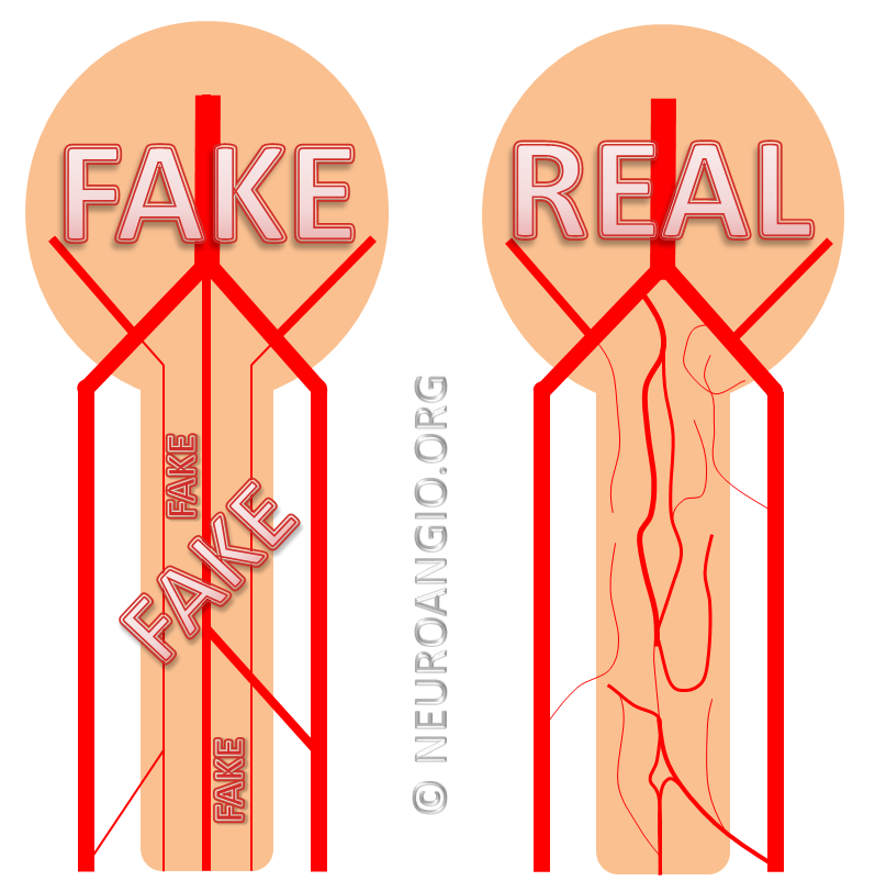
The basic arterial vertebrospinal vascular unit consists of two segmental vessels, left and right, arising from the dorsal surface of the aorta. The vessel curves posterolaterally in front of the vertebral body, and sends small branches into its marrow. In front of the transverse process, the segmental artery bifurcates into a dorsal branch and an intrercostal branch. The intercostal segment supplies the rib and adjacent muscle and other tissues. The dorsal branch feeds the posterior elements and, via the neural foramen, sends branches to supply the local epidural and dural elements, as well as a radicular artery to nourish the nerve root. At some levels, the radicular artery is enlarged because, instead of supplying local neural elements, it maintained its embryonic access to the anterior spinal artery. At this level, the artery is called “radiculomedullary” because it also supplies a large segment of the spinal cord. Various other arrangements are seen, for example when radicular artery supplies portions of the dorsal spinal cord, a discontinuous network which is often misrepresented in venerable anatomical texts as a continuous system of two posterior spinal arteries. This is the basic arrangement of spinal supply.
The system varies in the cervical, upper thoracic, and sacral segments (i.e. exceptions are greater than the rule) but the basic principle of segmental dural and radicular vessels supplying neural tube elements is a very useful guide. Variation comes chiefly in form of segmental vessel origin — whereas descending aorta serves this puprose for most thoracic and lumbar segments, the vertebral artery, subclavian branches (costocervical trunk for example), supreme intercostal artery, and median sacral artery (effectively a diminuitive continuation of the aorta below the iliac bifurcation) play this role at the appropriate segments. These vessels of origin are part of the gridline of longitudinal channels which form to connect embryonic segmental vessels. For example, the vertebral artery represents a confluence of discontinuous embryonic channels termed the “longitudinal neural system” into a single trunk. This, in part, explains multiple variations and duplications encountered in the vertebral territory.
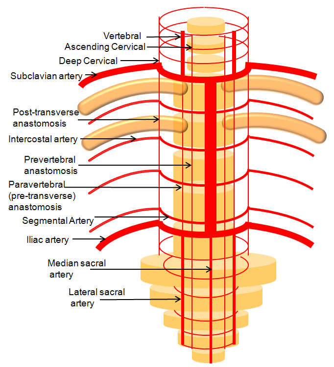
Figure 1: Somatotopic organization of the vertebrospinal arterial vasculature, highlighting segmental vascular organization of the vertebrospinal axis and homologous longitudinal anastomoses along its entire length.
As you can see, numerous longitudinal vessels exist throughout the vertebrospinal axis, often with the same vessel going by several different names, for historical reasons. For example, see above for homology between the lateral spinal, pre-transverse, and deep cervical arteries. The segmental arrangement is particularly modified in the cervical region, where longitudinal vessels are dominant — most obviously the vertebral arteries. It is important however to recognize the existence of segmental vessels connecting the three dominant cervical longitudinal arteries (ascending cervical, vertebral, and deep cervical) in terms of their anastomotic potential and its implications for both collateral revascularization and inadvertent embolization during interventional procedures.
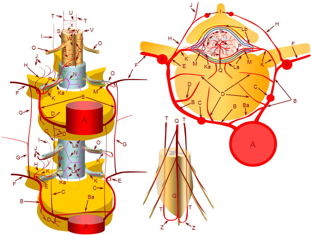
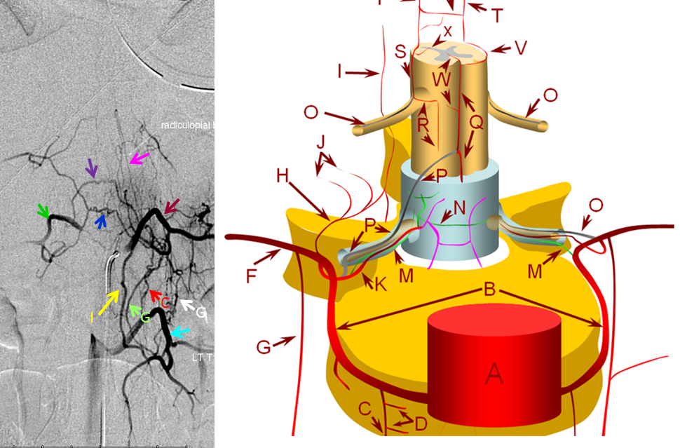
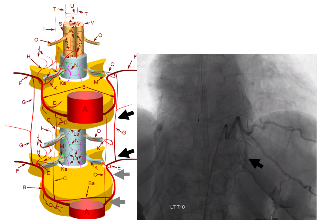
The following diagrams provide a basic view of relevant arterial anatomy of the spinal elements, serving as a guide for interpretation of subsequent catheter angiography illustrations.
A – aorta; B – segmental artery; Ba – intersegmental arterial anastomosis; C – prevertebral anastomotic network; D – direct vertebral body feeding arteries; E – dorsal spinal artery; F – intercostal/muscular artery; G – pretransverse anastomotic network; H – dorsal division of the dorsal spinal artery; I – post-transverse anastomotic network; J – muscular branches of the post-transverse anastomotic network; K – ventral division of the dorsal spinal artery; Ka – radicular artery; La – ventral epidural arcade; Lb – dorsal epidural arcade; M – nerve root sleeve dural branch of the ventral division dorsal spinal artery; N – dural branch of the ventral division dorsal spinal artery; O – radiculopial artery; P – radiculomedullary artery; Q – anterior spinal artery; R – mesh-like pial arterial network; S, T – posterior spinal artery; U, V – pial arterial network (a.k.a. vasocorona) anastomoses between anterior and posterior spinal arterial systems, W – sulco-commissural artery, X – rami perforantes of the peripheral (centripetal) system, Y – central (centrifugal) system of sulcal arteries, originating from pial network of the cord; altogether, the pial network and rami perforantes (R+Y) are called the vasocorona or corona vasorum; Z – rami cruciantes (a.k.a. crux vasculosa, a.k.a. rami anastomotici arcuati)
In the following examples, nomenclature using the above letters will be used for correlation.
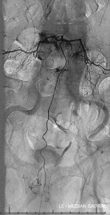
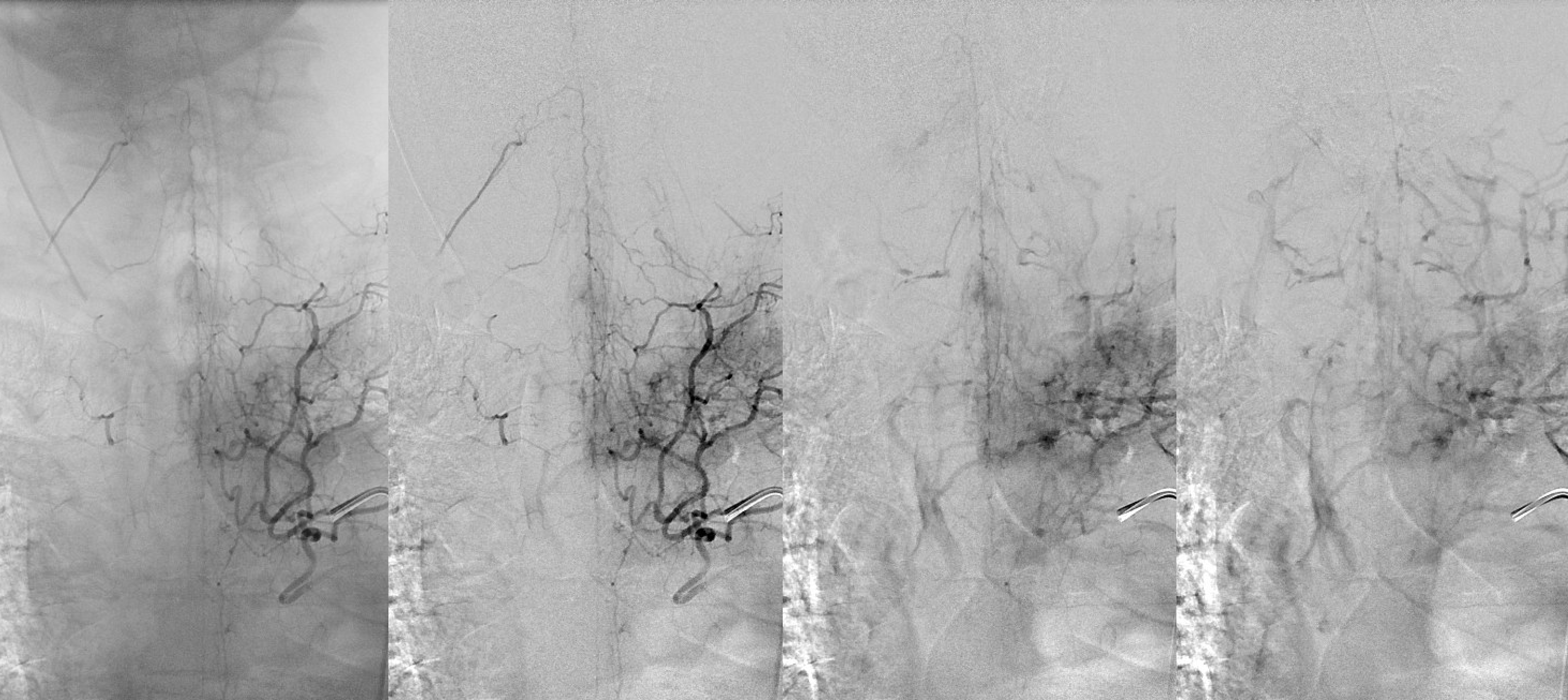
Aorta and segmental vessels. Many spinal angiograms start with imaging the biggest vessel in the body. Some are surprised to discover that these segmental lumbar and intercostal arteries (red) are actually not that small (between 1 and 2 mm diameter typically) — most can be easily engaged (and occluded) with a 5F catheter. The aortic injection gives a roadmap, may identify a particularly large fistula, and show which levels may have missing segmental arteries, thereby obviating a frustrating search. In this angiogram of a patient with a dural fistula, a congested spinal cord vein (light blue) can be seen in the venous phase (dark blue). Celiac trunk (orange) and renal arteries (yellow) are also labeled.
anterior
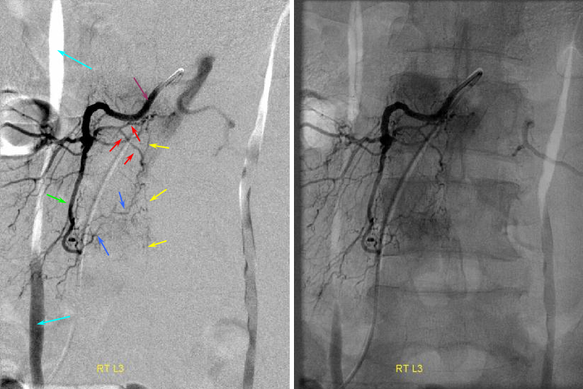
Typical Lumbar artery (segmental artery) injection. During spinal angiography, the segmental artery is selected with an appropriate 4F or 5F catheter (RDC, SAS). Injection rates are 1-2 cc/sec for as long as you think you need it, typically 2-4 seconds. Frame rates vary from 1-3 per second, and should not exceed 3 unless particularly necessary (to visualize microanatomy of a high flow fistula, for example). When dural or other fistula is suspected, multiple levels may need to be interrogated. One can easily go through 300 ml or more of contrast, so be aware. For metastatic disease, the search may be more focused. It is helpful to view the angiogram in both subtracted and native views to appreciate both fine vascular detail and bony landmarks.
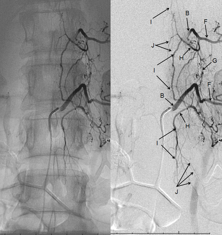
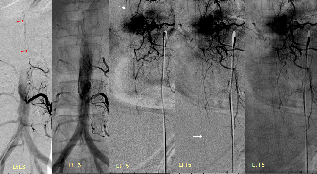
The lumbar artery (purple, B) is relatively selectively injected, with trace opacification of hte contralateral left L3 lumbar artery due to proximity of the left and right orifices to each other. Since there is no rib, the artery does not have a prominent “intercostal” component. The arteries of the dorsal branch (red, H, J) supply the lamina and adjacent tissues, with anastomosis to the spinal process arterial arcade (yellow, I). You can see continuation of this arcade inferiorly, NOT to be mistaken for the anterior spinal artery or other spinal artery. The anterior spinal artery is straighter and has a characteristic radiculomedullary hairpin turn (see below). A large paravertebral anastomotic branch (green, G) is present, which opacifes ipsilateral L4 level dorsal branches (blue, H, J). No radiculomedullary artery is seen at this level.
Common lumbar trunk: Especially in the lower spine, single left and right lumbar artery origins are common. Absent levels are also common, usually supplied via paravertebral and prevertebral anasomoses.
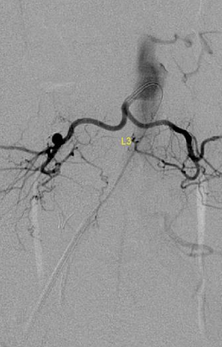
Paravertebral anastomotic network — typically, this is the dominant longitudinal anastomotic connection between adjacent segmental arteries. It is particularly well visualized in young, normotensive patients. Technical considerations are also important — having the catheter well-wedged into the ostium of the segmental artery, as well as longer, higher volume injections (within reason, of course), are key to opacifying all kinds of collaterals. The paravertebral network is located along the lateral aspect of the vertebral body, adjacent to the sympathetic chain, for example. A well developed paravertebral network (blue, G) is present. The catheter (red) is engaged in a lumbar artery (brown, B) and via this network opacifies the lumbar artery of the level immediately above (purple) and immediately below (pink). Notice the spinous process arcade again (black, I). This network ensures virtual impunity for atherosclerotic or iatrogenic occlusion of a proximal segmental artery. More care should be excercised at radiculomedullary artery levels.
Multiple longtitudinal anastomotic networks — prevertebral, paravertebral, spinous process
In this patient, all three networks are demonstrated — stereoscopy is very helpful to decide which is which. Also notice prevertebral transverse and retrocorporeal networks at same level.
C – prevertebral anastomotic network; G – paravertebral anastomotic network (can opacify adjacent levels with strong injection, or supply adjacent level in case of intercostal artery hypoplasia/aquired stenosis); I – spinous process branch and associated anastomotic network connecting spinous processes; Blue — precorporeal anastomotic network (not shown in diagram); blue — retrocorporeal anastomotic network (pink color vessels in diagram, and see section below); light blue — left L1 segmental artery; brown – left T12 segmental artery; dark green — right T12 segmental artery; pink – radiculopial artery.
Another demonstration of multiple longitudinal anastomoses:
Lumbar segmental artery injection, demonstrating a well-developed post-transverse anastomotic network (I) visualized through the ventral division (H) of the segmental artery (B), with its muscular branches (J), as well as the pre-transverse anastomosis (G), both contributing to collateral visualization of the adjacent cranial segmental artery (B). F – muscular artery, homolog of the intercostal artery.
Retrocorporeal arterial network
This characteristic diamond-shaped network behind the vertebral body (in the epidural space dorsal to the posterior vertebral body cortex, also known as anterior [with respect to the spinal cord] epidural space) marked with “L” on the diagrams above, constitutes the primary anastomotic connection between left and right segmental arteries of the same level. Like everything, else it is variable in prominence based on developmental and other considerations. A good injection can usually opacify parts of the network, but it becomes quite obvious once the diamond-shaped configuration corresponding to left and right superior and inferior contributors to the diamond are revealed. One way to improve visualization of the network is via an injection adjacent to a dissected segmental artery.
More retrocorporeal arcade images, demonstrated to great advantage in a young patient
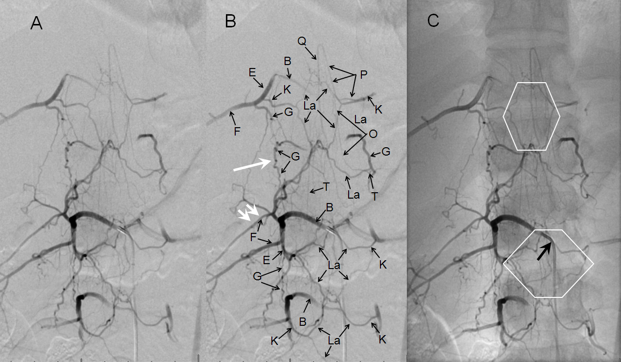
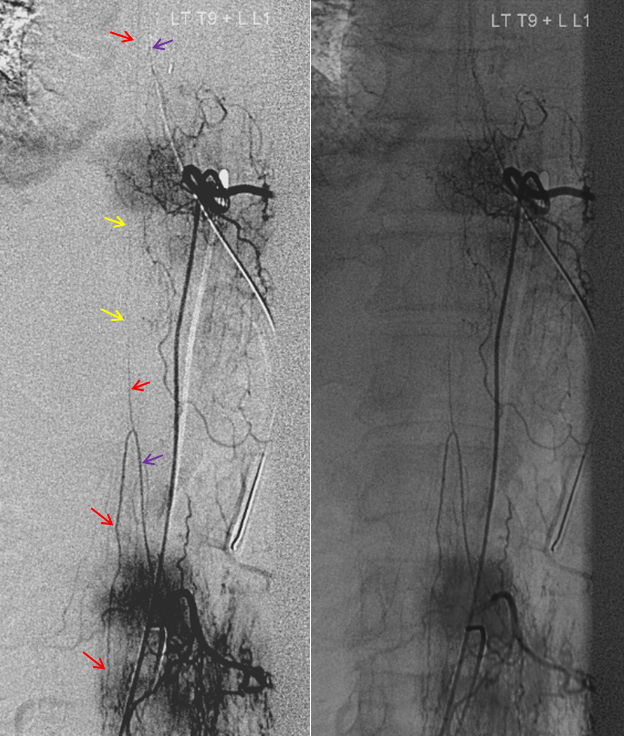
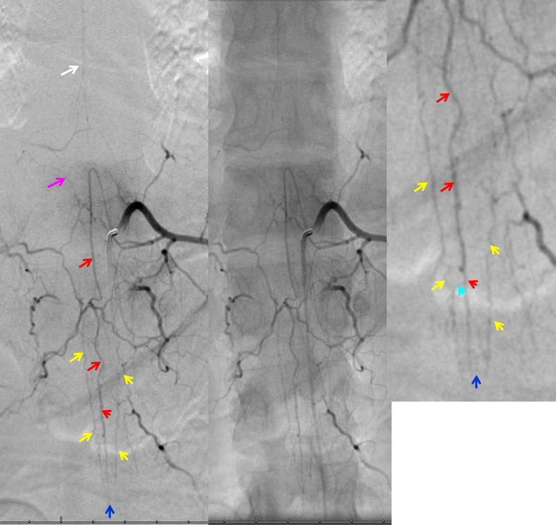
T12 segmental artery injection of a young, normotensive slender patient, providing exquisite visualization of the various trans-segmental anastomoses, demonstrating a hexagon-shaped multilevel anterior epidural arcade (La), and prevertebral anastomoses (G). Notice developmental hypoplasia of the right T11 segmental artery (single white arrow, one level above the catheter), with a corresponding small intercostal artery caudal to its normal position (double white arrow). Both radiculomedullary (P) and radiculopial (O) arteries are present, the former demonstrating its characteristic midline course.
Another injection, which happens to preferentially opacify the retrocorporeal network
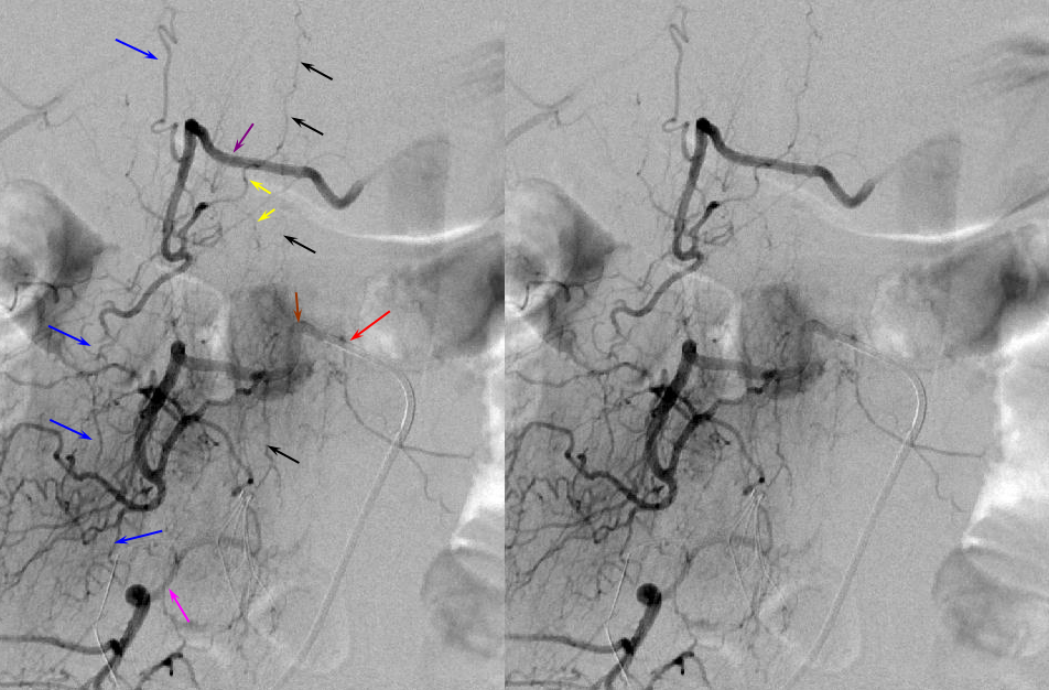
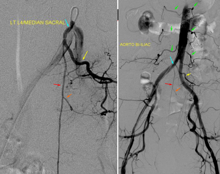
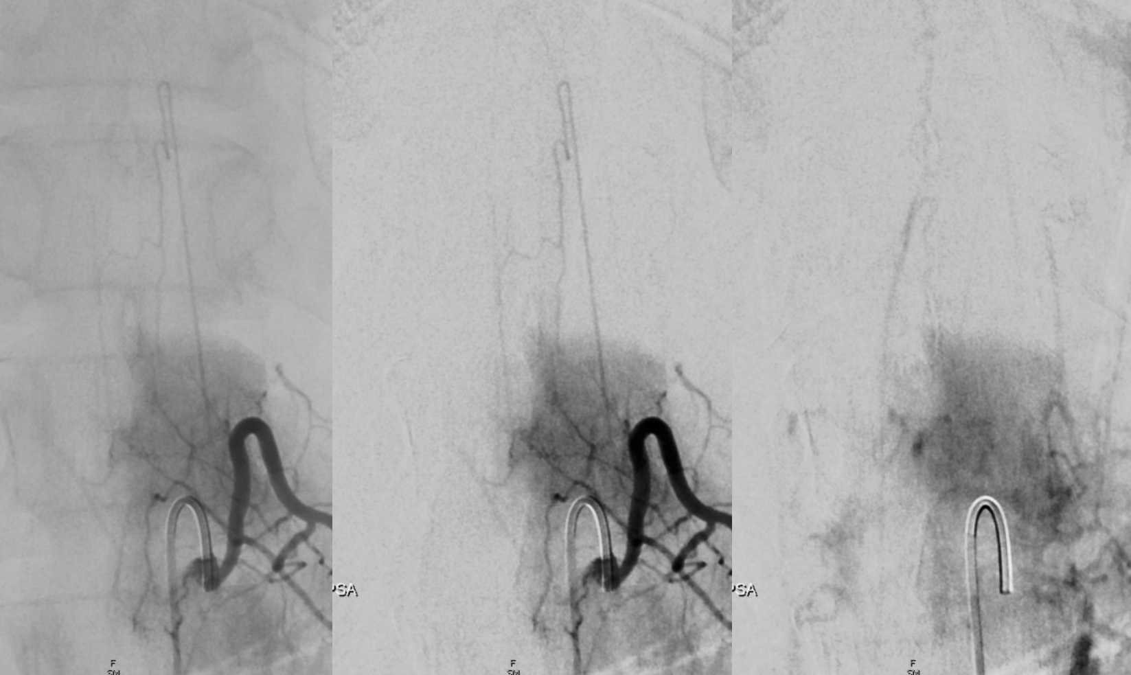
The median sacral artery — continuation of the aorta, the median sacral artery usually comes off the carotid bifurcation, and can be most easily engaged via some kind of recurved catheter (It is the artery to the tail of countless species which happen to have one). As a homolog of the aorta, it gives origin to segmental vessels of the sacrum. Thus median sacral artery injection is in fact a sacral aortogram — opacifying multiple segmental sacral branches. It is a must see artery when looking for a fistula. Here, the median sacral artery (red) originates from the left L4 branch (blue and yellow). Lumbar segmental vessels seen on the aortogram are shown in green.
Median Sacral Artery and Lateral Sacral Arteries –– the lateral sacral arteries are longitudinal vessels wich are homologous to the paravertebral (pre-transverse) anastomoses in the thoracolumbar segments and to the vertebral artery in the cervical spine. They arise from proximal internal iliac arteries, and can be seen from either internal iliac or median sacral injections, as well-demonstrated below:
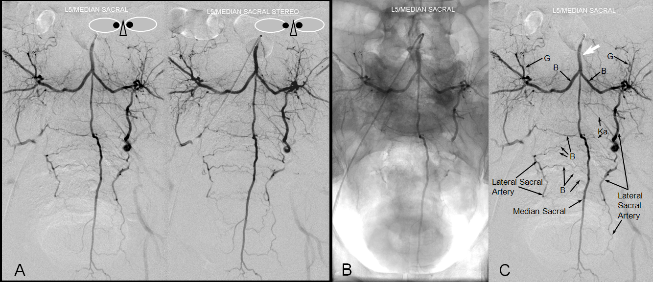
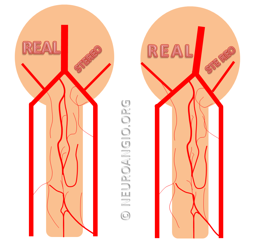
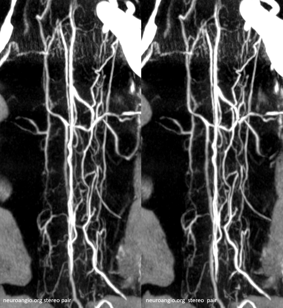
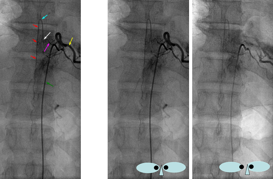
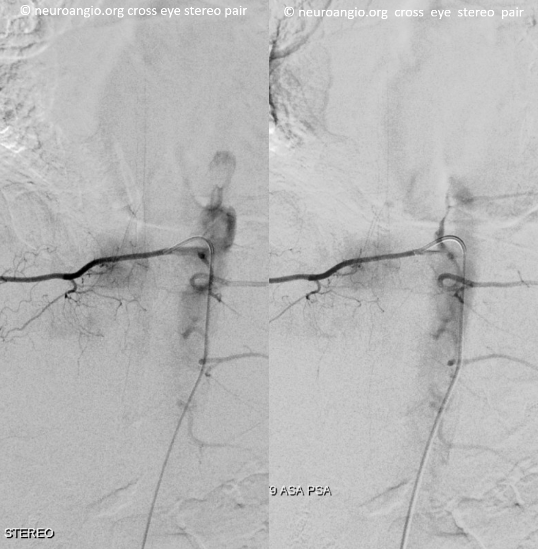
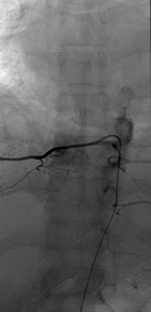
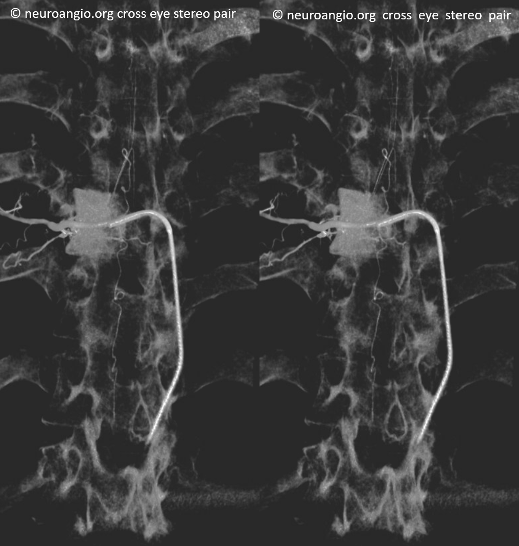
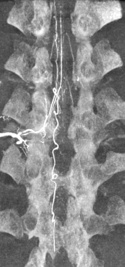
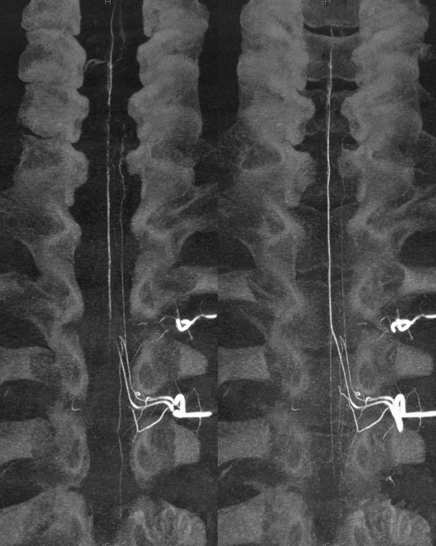
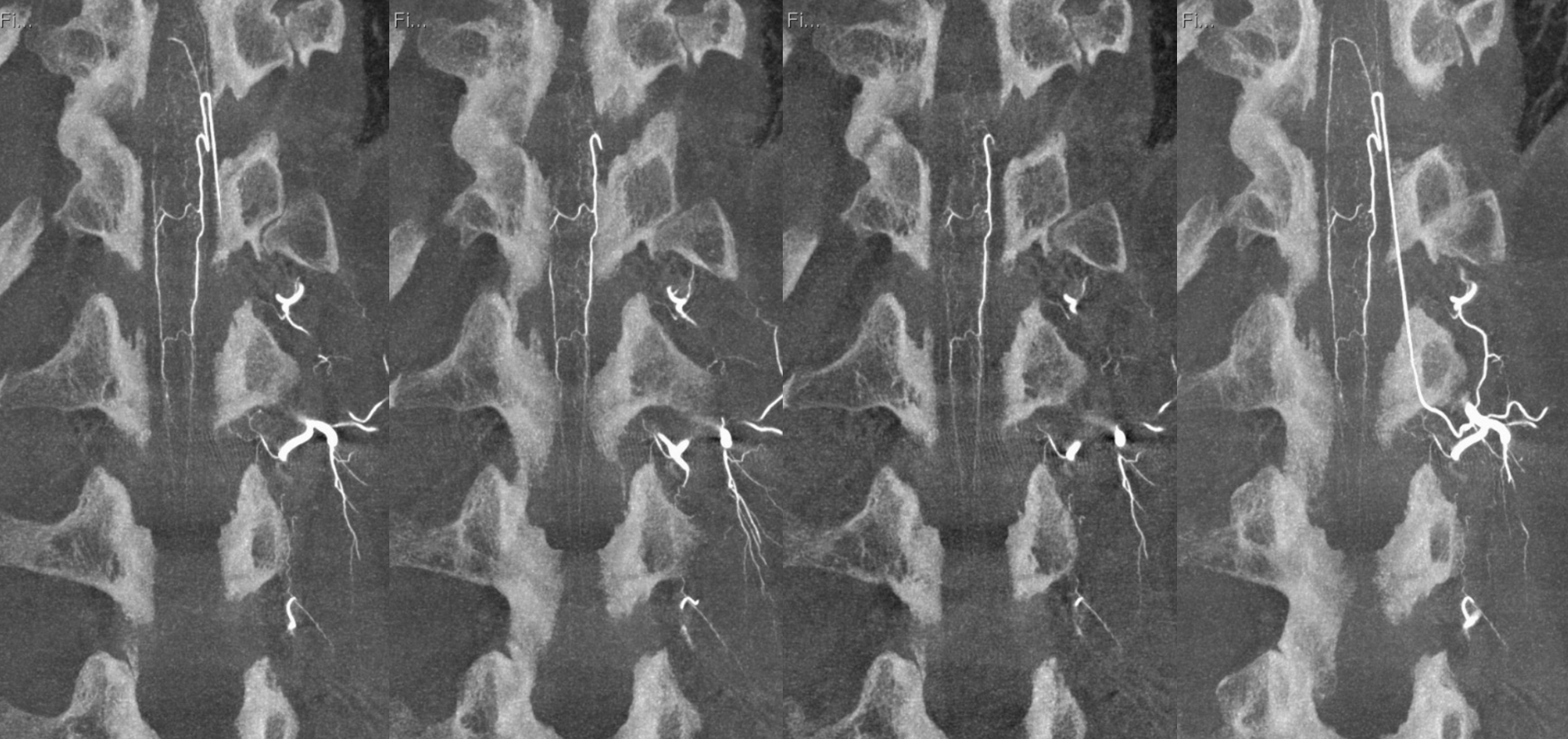
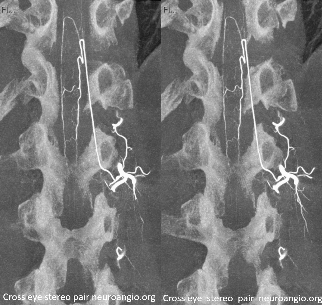
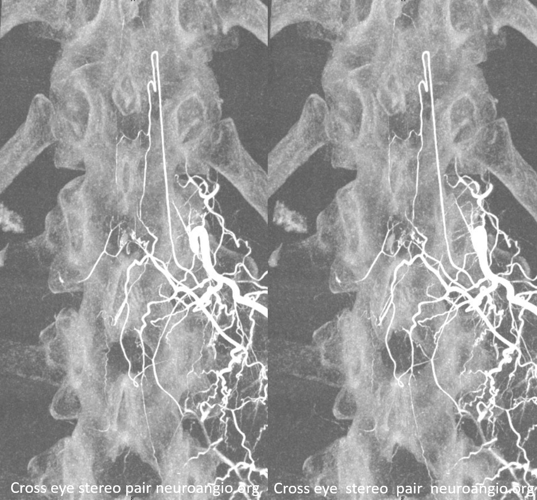
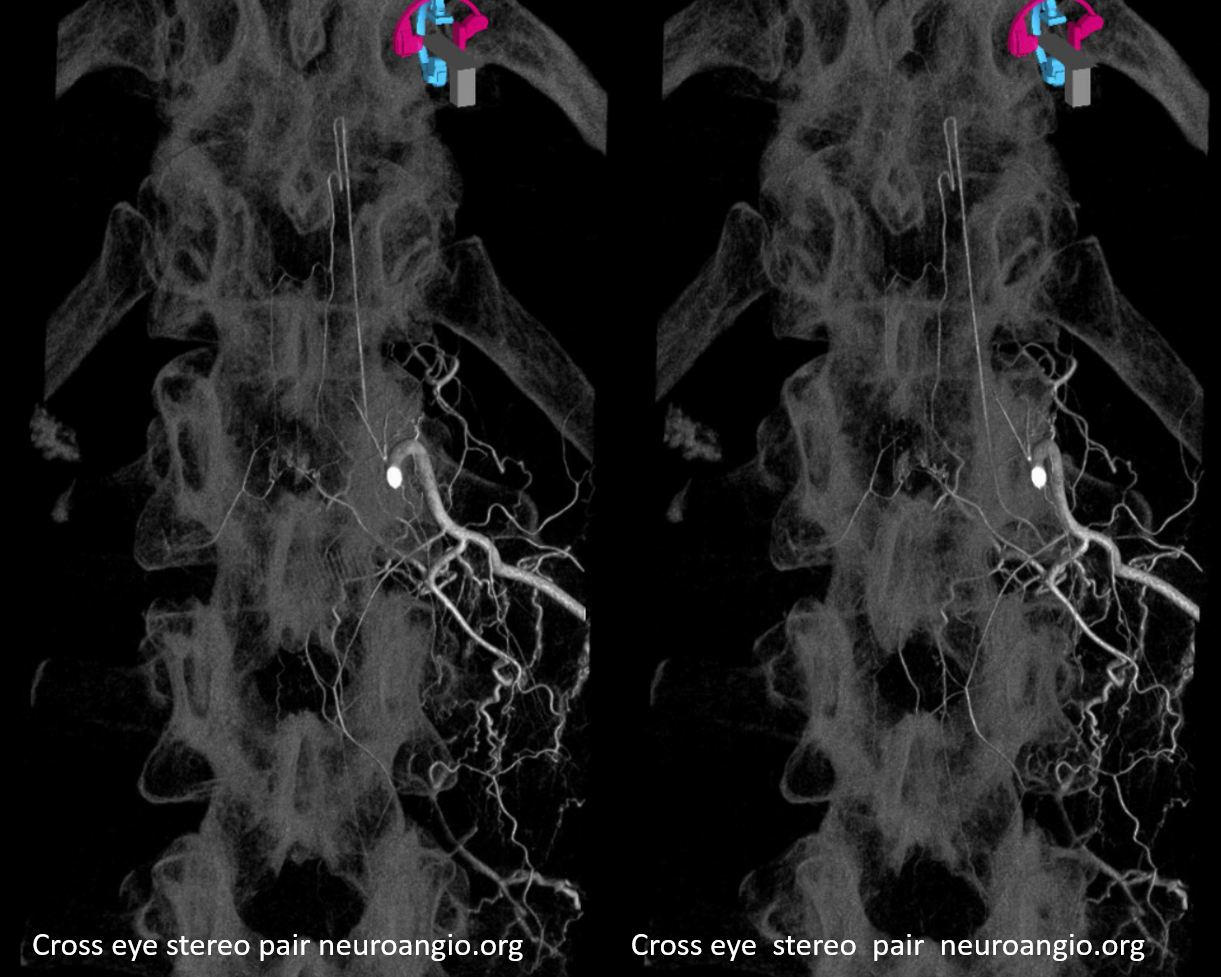
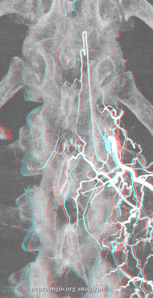
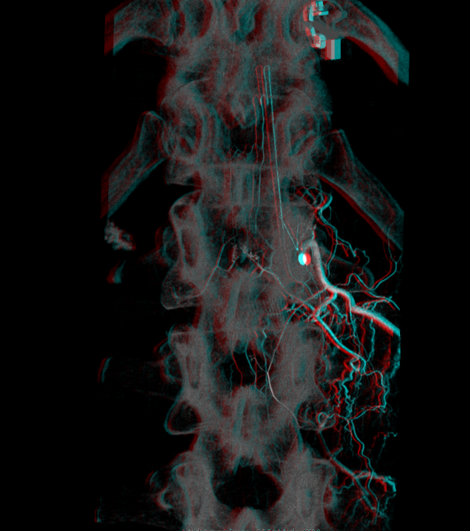
Inferior lumbar and sacral anatomy. A – stereo pair, B – native image, C – legends: Selective catheterization of a common L5 segmental trunk (white arrow), also giving rise to the median sacral artery (normally arising from the region of aortoiliac bifurcation). The injection opacifies bilateral L5 and sacral segmental arteries (B), and the prevertebral anastomotic network (G), which is homologous with lateral sacral arteries. A – stereo pair; B – native image; C – Labels.Here is an injection of the lateral sacral artery (center) with adjacent images of bilateral internal iliac injections, demonstrating existence of extensive collateralization between the internal iliac and median sacral systems by opacifying the same arteries which are labeled with the same color arrows. The purple and red arrows point to the lateral spinal artery seen from both median sacral and internal iliac injections. Green arrows outline the remainder of the lateral sacral system, best seen from medial sacral in this case
Anaglyph stereo
Median sacral artery (purple) giving rise to multiple sacral segmental arteries (red) and to a lumbar artery (yellow)
In this example, median sacral artery arises from a common L5 trunk.
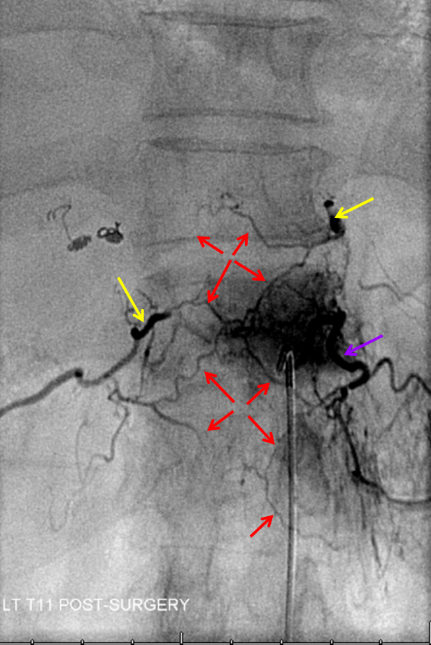
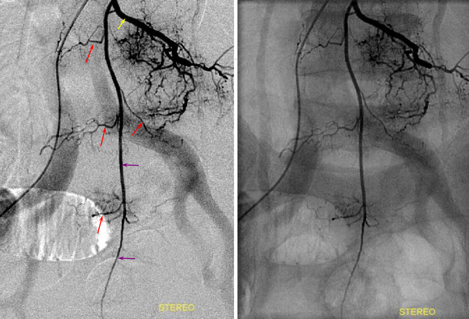
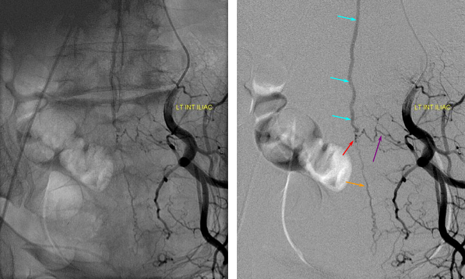
Below the aortic bifurcation, segmental arteries can be visualized by injection of the median sacral artery (above) and internal iliac arteries, via the lateral sacral artery (see figure 1 above) The importance of iliac artery investigation cannot be overstated. The patient whose images are shown below underwent two spinal angiograms for investigation of suspected dural fistula, based on classic MRI appearance of cord congestion and serpiginous vessels in setting of progressive neurologic decline. Only on third time around was the left internal iliac artery interrogated, easily disclosing a dural fistula, supplied by a segmental artery (purple) and collateral probably dural artery (orange) with fistula point (red) and draining into a radicular vein (light blue) connected to the spinal venous network (above, not shown).
ANTERIOR SPINAL ARTERY (ASA): Cervical, thoracic, lumbar, and conus regions.
Overview: the anterior spinal artery (Q) develops as a longitudinal vessels connecting transversely oriented segmental arteries, as discussed at length above. It is located on the ventral surface of the cord, adjacent to the ventral median fissure of the spinal cord. It varies in size, more or less based on the amount of gray matter at the given segment. As such, its size is substantially larger in the cervical and lumbar segments (might be 500-750 micrometers in diameter), as compared with slender mid-thoracic size. As such, one end of the ASA has limited to no capacity to support the other should its dominant radiculomedullary supply fail. The arterial supply to the ASA consists of radiculomedullary arteries (P), which represent persistence of embyronic segmental connections between the aorta and the developing ASA. Their number varies, perhaps being 6-10 in the human. Some are quite small and, as such, below resolution of in vivo spinal angiography. The larger cervical and lumbar ASA segments are associated with larger radiculomedullary arteries to supply them — the famous artery of lumbar enlargement (Adamkiewicz), and the less well known (radiculomedullary) artery of the cervical enlargement, known to some neurovacular anatomists as the artery of Lazorthes. The Lazorthes most commonly arises from lower cervical vertebral artery, though not infrequently from deep cervical or supreme intercostal vessels also. The Adamkiewicz comes off between T9 and T12 in 75% of cases, more commonly on the left (which means, to me, that 1/4 of the time, its somewhere else). Not infrequently, there are two relatively smaller radiculomedullary arteries at the lower thoracic spine, instead of one big Adamkiewicz. At the bottom of the cord, the anterior spinal atery is typically connected to posterior spinal arteries (T) via what paired arteries (Z) which go by many names (such as rami cruciantes), forming a kind of arterial basket (see above diagram, and below for angio images). Visualization of this basket is critical if you wish to call a spinal angiogram “complete”.
Cervical ASA:
Bilateral vertebral artery study in anterior spinal artery supply. Sometimes, in intracranial work, it becomes important to know the location of the anterior spinal artery with respect to the cervical spine. For example, vertebral artery dissection may be treated differently depending on whether it involves ASA origin. Vertebral artery sacrifice should not be undertaken until the location of the ASA has been considered. For example, closing a vert immediately distal to radiculomedullary ASA contribution, without other runoff branches, risks possibility of the vert stump thrombosing back and closing this ASA segment. Collaterals are often insufficient to maintain cord viability.
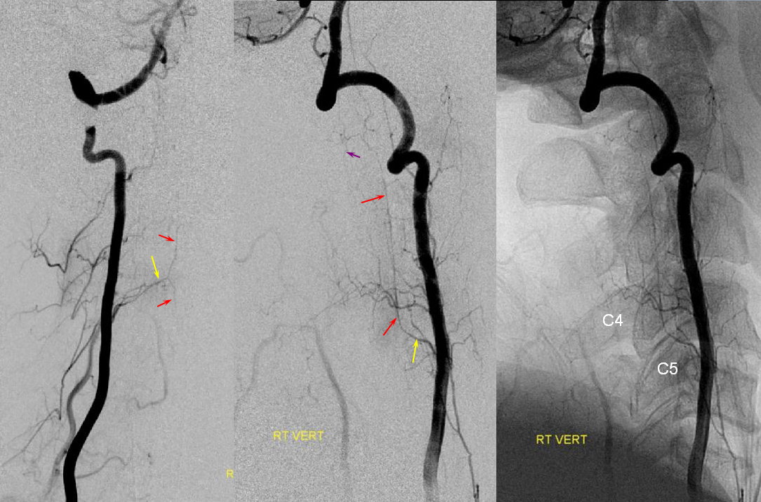
Just seeing one radiculomedullary ASA contributor may not be enough in some cases — to truly define full anatomy one must opacify the entire ASA system. If a given radiculomedullary artery only shows the ASA inferior to its level, then one must keep looking for additional rostral sourses. For example, if one sees an ASA from C5 down in a case where ascending or deep cervical embolization is required, it would be advisable to find the source of superior cervical supply before concluding that ASA territory is safe. In this case, the upper cervical cord segment is supplied from the left C5/6 level, while the inferior cervical cord from the right C4/5 segment.
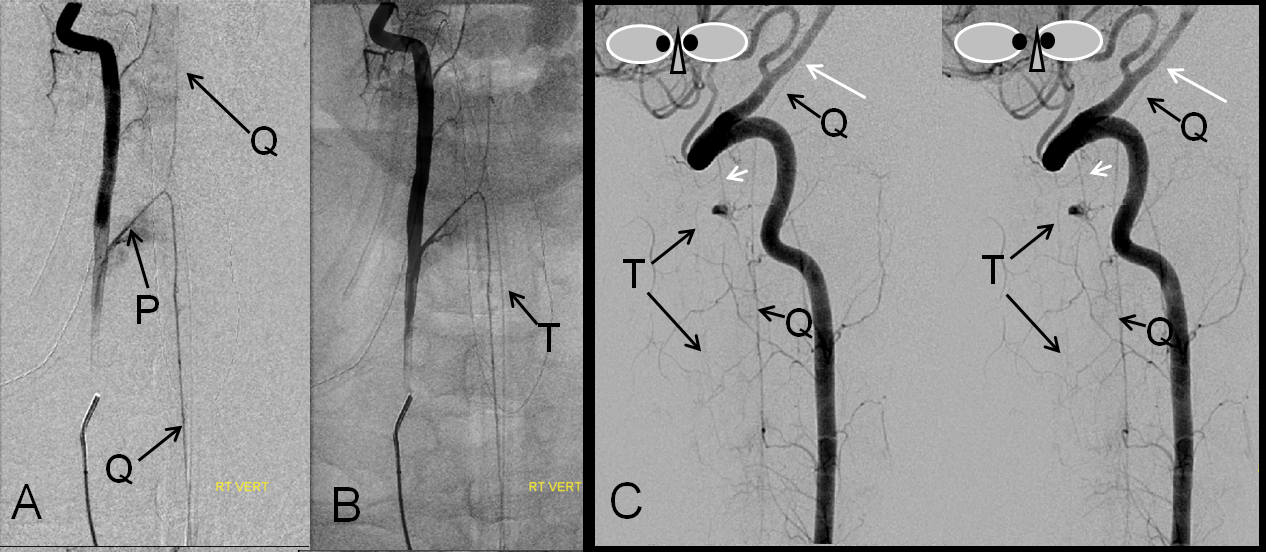
Left vertebral (top) and right vertebral (bottom) set of images from the same patient, demonstrating full length of cervical anterior cerebral artery supply from the vertebral system. The lower portion of the cervical ASA (red, Q) is fed via the left C5/6 radiculomedullary contributor (yellow, P), which also happens to supply the posterior spinal artery network (purple, S, T). The upper ASA segment is fed by the right C4/5 radiculomedullary artery (yellow, P) seen on the image below. The radicular portion is labeled in yellow. ASA=red; Posterior spinal arteries = purple
Another view of cervical radiculomedullary artery (of Lazorthes) arising from inferior vertebral (C6 segment). This kind of dominant supply is seen less frequently for the cervical spinal cord than it is for the thoracolumbar enlargement in case of the artery of Adamkiewicz.
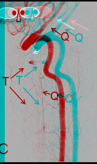
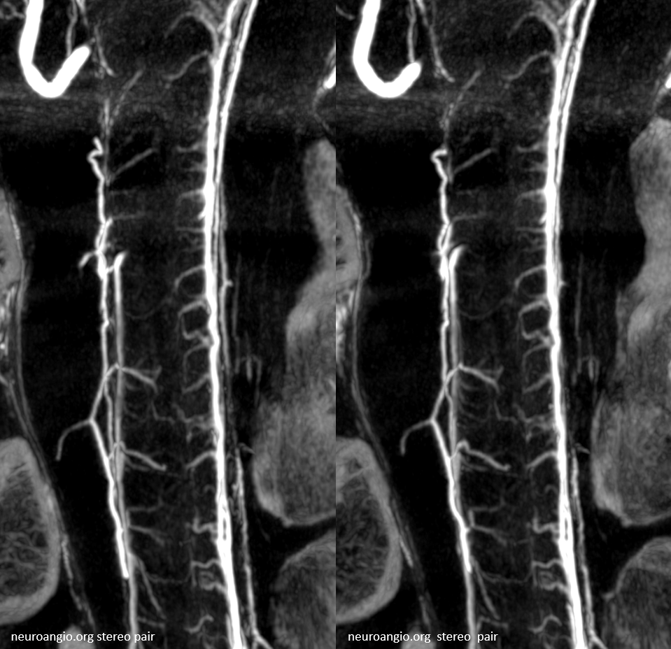
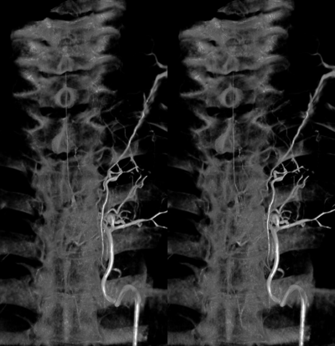
A, B – Frontal and C — lateral stereo pair projection digital subtraction and native angiographic views of right vertebral artery injection, visualizing a dominant cervical radiculomedullary artery (P, artery of Lazores) and the anterior spinal artery (Q), anastomosing with its basilar homolog (long white arrowhead). Very faint posterior spinal artery (T) is best seen in stereo, as well as the lateral spinal artery (short white arrow).
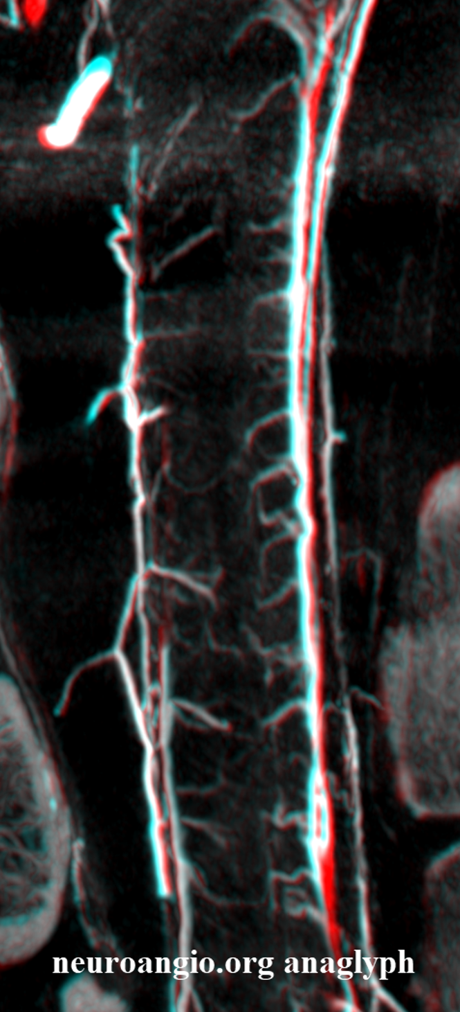
Anaglyph stereo
Another view of the cervical cord, this one also displaying the posterior spinal (brown) axis and the pial vessels (yellow) which connect the anterior and posterior axes on the pial surface of the cord. Visualizaton of the pial network of the thoracolumbar cord is limited by the body habitus of the patient, which works against resolving small vessels even under conditions of perfect paralysis and apnea. The situation is much better in the cervical spine. Notice the discontiguous nature of the posterior spinal network, in contrast to the straight anterior spinal artery.
Although balanced supply to the cervical cord is more common, and most of the time it comes from the cervical vert, occasionally the typically small distal intracranial vertebral artery supply is dominant, as in this case. It is important to pay attention to this when flow diversion methods are used in the distal vertebral artery.
Anterior lateral and posterior (aka lateral) spinal arteries
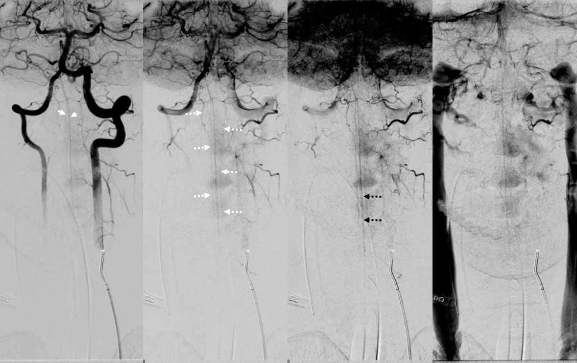
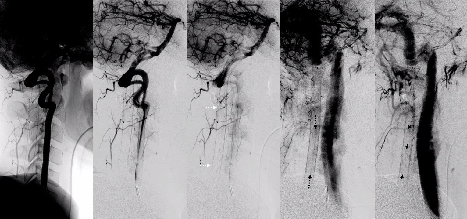
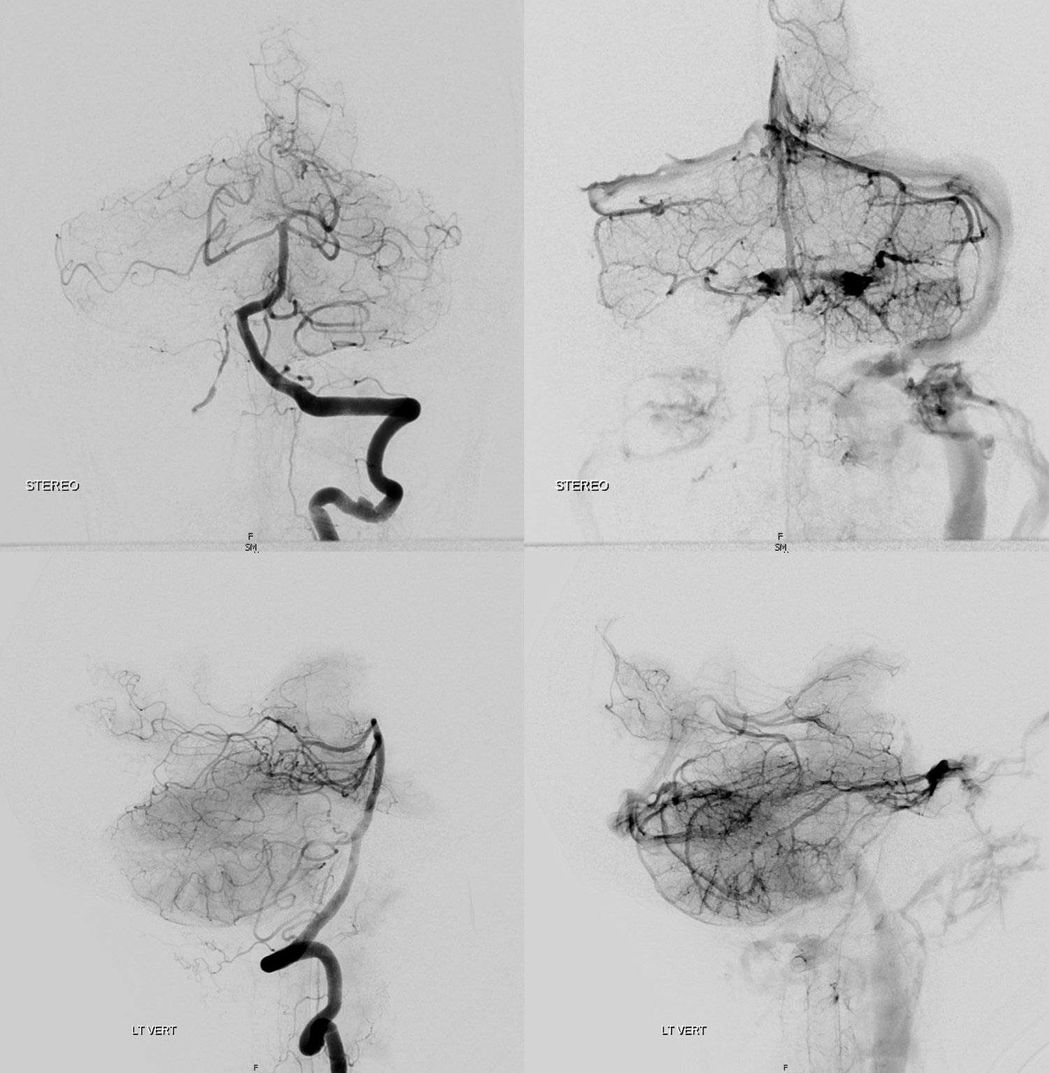
Look at this! Ridiculously “one-sided” origins of all three major systems — the anterior spinal and both posterior spinal arteries are supremely well-seen — originating from distal right vert (asa) and both PICAs (posterior spinals). This is most unusual. Frontal views show duplicated upper cervical asa (white arrowheads), long contiguous posterior/lateral spinal arteries (dashed white arrows), and faintly seen sulco-comissural arteries (black dashed arrows)
Lateral views show extremely well the posterior spinal axis (white dashed arrows), the position of spinal cord in the osseous spinal canal (leftmost image), a beautifully seen faint line of sulco-comissural vessels terminating in the depth of the ventral median sulcus (black dashed arrows), and circumferential / transmedullary spinal veins (black arrowheads)
Rotational angiography/DYNA shows bilateral vert origins of anterior spinal axis (white arrows) and lateral / posterior spinal arteries (dashed white arrows) with several prominent coronary arteries — short arteries running transversely along the circumference of the cord (white arrowheads), opacifying the posterior cord (black arrows)
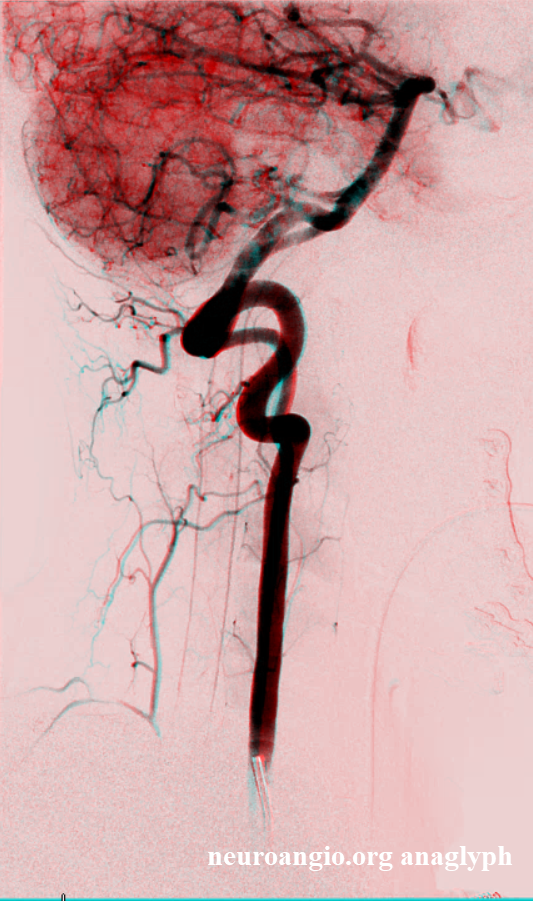
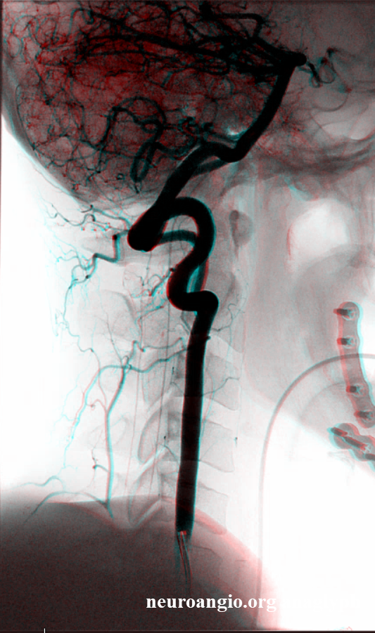
Anaglyphs
They dont read books
Rule is there are no rules. In at least 1/3 of us there is no real discrete anterior spinal artery over the cervical segment according to Lazorthes, and he knew it. Angio findings confirm this and there are large posterior networks present. The lateral /posterior spinal network can be supplied by the anterior spinal one, when its prominent. So, study every subject. Here, for example, angio with fairly prominent anterior and posterior/lateral spinal systems, with good venous phase to show it.
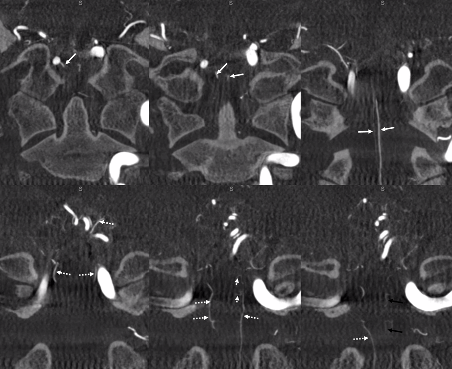
Below are MIP images of a 10 second DYNA CT — thus minimizing venous phase — some veins show up by then, but arteries are much brighter. Look at some really nice sulco-commissural arteries supplying their respective hemicords. There are large vasocorona draping the ventral cord in most images. Prominent posterior spinal on most images also.
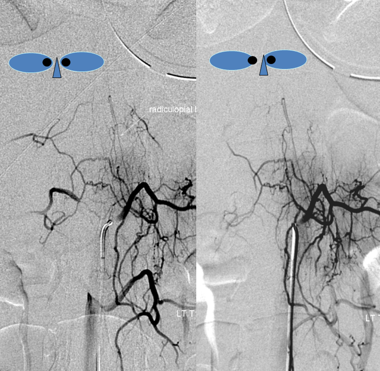
Amazing images of the sulco-commissurals and the posterior/lateral spinal network, with the vasocorona connections. No labels.
Labels. The posterior / lateral spinal is inside solid white oval. The lateral spinal is smaller and more ventral. Middle image — vasocorona connecting to lateral spinal artery. Dashed white oval — same — ASA supplying bilateral lateral cord. Dashed black oval — from the back — posterior spinal more prominent, lateral spinal smaller and shorter.
Rich collateral network of vertebral system
The connections between cervical anterior spinal system and the myriad other vessels in the neck are plenty — bilateral vertebral, occipital, anterior cervical, deep cervical, ascending pharyngeal — many ways to get in trouble during embolizations. Most of these connections are relevant in terms of vertebral artery anastomoses (see vertebral artery page). Here is a superb illustration of these connections in a patient with a hypoplastic vert, where the diagnostic catheter is occlusive at the origin and therefore allows for reflux into all kinds of adjacent vessels — all images courtesy of Dr. Eytan Raz
Same with labels and lateral. Red – ASA, white – radiculomedullary, yellow — epidural arcade, purple — odontoid arcade, blue – muscular branch ascending pharyngeal; black – neuromeningeal trunk, ascending pharyngeal; orange — pharyngeal trunk, ascending pharyngeal; green — occipital; pink — deep cervical; brown – ascending cervical
Now, for one of the most amazing stereos on the website:
The radiculomedullary network is particularly well seen in pediatric population — like all anastomoses. Here is a normal vert injection of a 5 year old. Image courtesy Dr. Peter Kim Nelson. Also notice dual origin vertebral arteries — so technically the catheter is in the deep cervical artery. See links to these pages for more info
Anterior spinal artery duplication
Embryologic considerations dictate that both anterior and posterior spinal arteries are, so to speak, secondary vessels arising as a conduit between metameric arteries. This is also true in case of the vertebral artery, coming together as a fusion of the longitudinal neural system. This notion helps explain unusual variants such as anterior spinal artery duplication. In this patient with bilateral superior cervical dissections, it is likely that hemodynamic need resulted in hypertrophy of a rudimentary duplicated anterior spinal artery — at least it can be said that in the majority of patients were similar constraints invoke support of the anterior spinal collateral, there is still only one anterior spinal, as opposed to this case, where there are two. Frontal view of right vert injection shows high servical dissection (orange), the anterior spinal system (red, pink arrows) contributes to supply of the right PICA (black) via the C4 segment radiculomedullary artery (brown). Notice midline location on the frontal view and superimposition of the anterior spinal channels on the lateral view, confirming their anterior spinal nature. The odontoid arcade (white) also does the same, via its usual C3 segment radiculodural artery (purple)
Stereo of the same
Injection of the left vertebral artery reveals a healed, less severe superior vertebral dissection. In a mirror image fashion, the left C4 radiculomedullary artery (yellow) supplies the “left-sided” portion of the anterior spinal system (pink) which was also seen from the right vert injection. The odontoid arcade (blue) and its C3 radiculodural artery (green) are also well-seen.
Here is another patient with a very real-looking, undeniably paired or duplicated anterior spinal artery in the cervical segment (white arrows) courtesy Dr. Eytan Raz
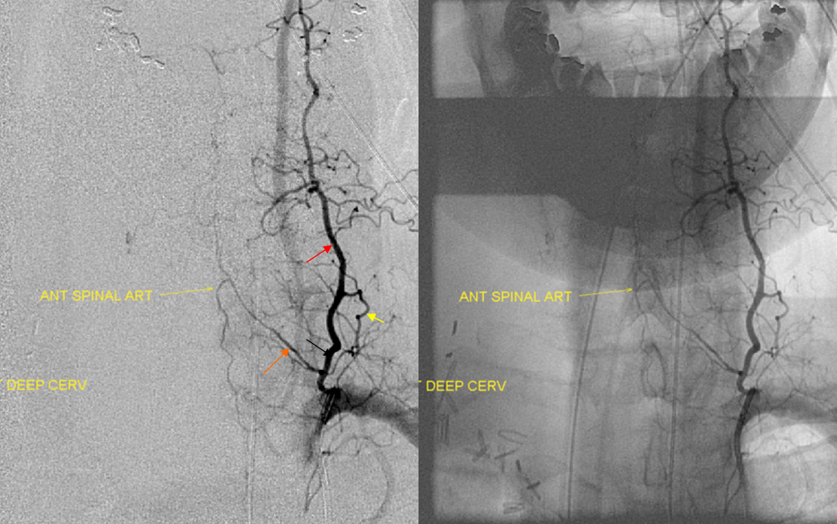
Deep Cervical origin of the radiculomedullary artery — second most common after the vert. At our institution, all cases of posterior fossa subarachnoid hemorrhage with no intracranial cause REQUIRE identification of the anterior spinal artery, as in ~10% of cases (in-house experience) the pathology turns out to be in the cervical spine.
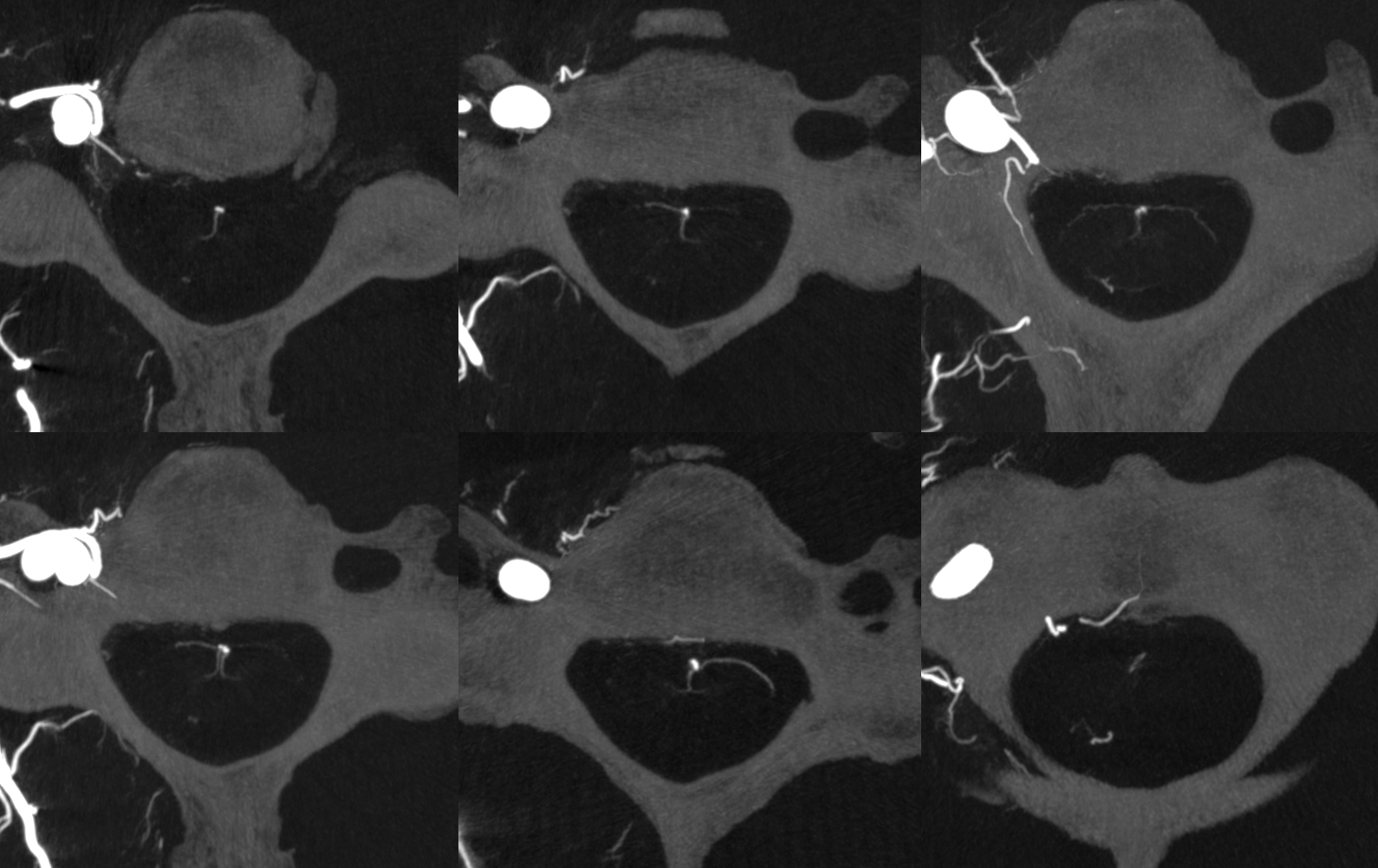
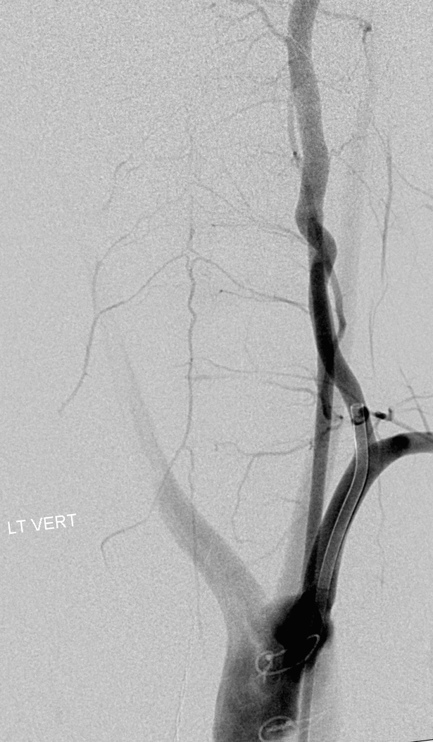
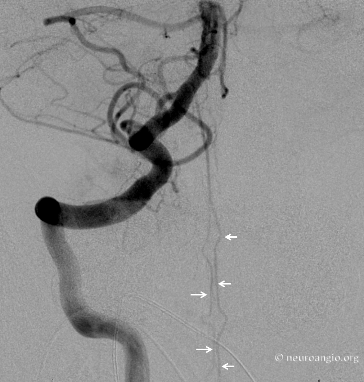
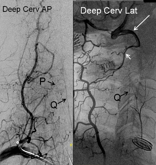
Anterior spinal artery (Q) origin from deep cervical artery, P= radiculomedullary artery; notice collateral opacification of the vertebral artery (long white arrow) via the C2 segmental artery (short white arrow).
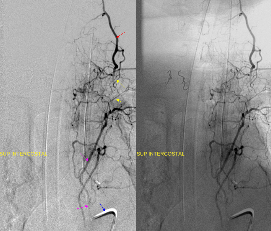
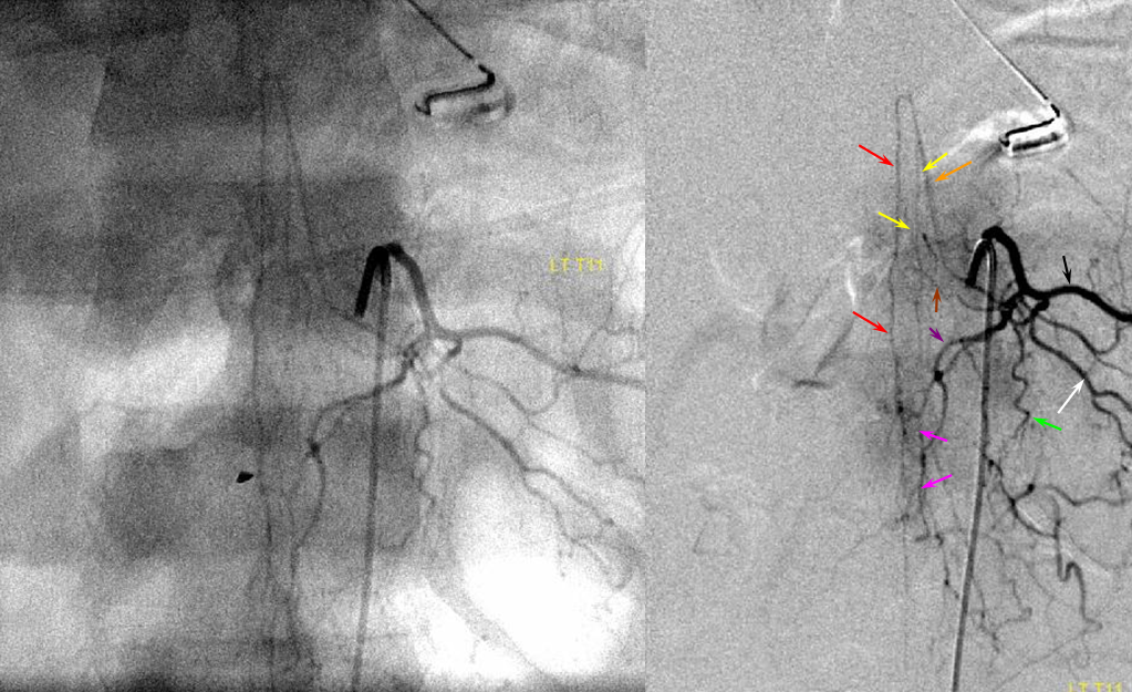
Another deep cervical origin — any longitudinal system can give origin to the radiculomedullary artery — in this case the radiculomedullar artery (orange) originates from the deep cervical branch (red). Notice also injection of supreme intercostal artery (pink, lower two images) with extensive deep servical artery anastomoses (yellow) through which the anterior spinal artery can be inadvertently embolized. The catheter, barely engaged in the supreme intercostal, is labeled in blue.
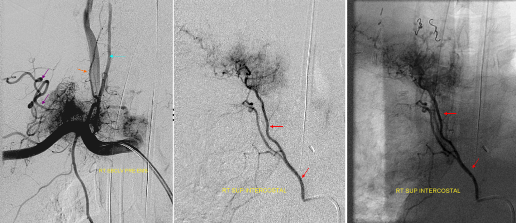
Same patient, contralateral side, demonstrating tumor blush (hemangiopericytoma) from the right subclavian injection supplied by costocervical (purple) and thyrocervical (orange) branches. An ipsilateral supreme intercostal (red) injection demonstrates extensive additional tumor, which is not apparent from the subclavian injection. The vert is labeled in light blue.
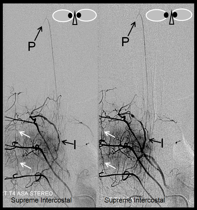
Supreme Intercostal Origin of Cervical Spinal Artery — occasionally seen as well, and important to know. The supreme intercostal and upper thoracic arteries can be difficult to catheterize sometimes, especially in patients with capacious dilated atherosclerotic aortas. We use a 4F or 5F RDC (which can be too small for the upper thoracic spine); if that does not work, one can try an appropriately-sized Cobra, or perhaps a Simmons 1. Sometimes, hand-shaping an RDC to produce a bigger curve (so as to push against the contralateral aortic wall) is more helpful than another catheter. In this case, the supereme intercostal was visualized via the T4 segmenal injection through a prominent paraspinal anastomosis (I)
stereo pair, supreme intercostal arteyr origin of the anterior spinal artery (same legends as above), visualized via T4 injection through a prominent post-transverse anastomosis (I). Notice transient contrast reflux into a cervical radiculomedullary branch (P); another longitudinal anastomosis (white arrow) between adjacent T3, T4, and T5 segmental arteries
Supreme intercostal artery (redP origin from the vertebral artery — another example of homology between various longitudinal anastomoses. Notice multiple intercostal arteries (yellow)
Stereo pairs, demonstrating posterior course of the supreme intercostal artery at the level of dorsal ribs
Collateral connections
Sometimes, only one injection is sufficient… In this case, injection of the left vertebral artery, through multiple super-efficient collaterals, opacifies nearly every vessel in the neck, as well as the entire anterior spinal axis. The arrows are unlabeled — please fill in yourself :-). Case courtesy of Drs. Potts and Riina
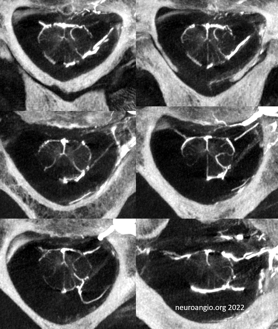
Cone Beam /Flat Panel CT evaluation of the Cervical Cord
Advances in cone beam CT are generating images with tremendous resolution throughout the spinal cord. However, imaging thoracic and lumbar cord is particularly challenging because of the small size of the cord compared with that of the body, requiring increased x-ray doses at lower image quality. This is much less of an issue in cervical spine, particularly when shoulders are low. Hense, the images can be truly astounding (by 2022 standards). Here are some examples — they are mixed arterial and venous — so many vessels are veins — see “Spinal Venous Anatomy” page.
Below is typical VR image. See anterior and lateral spinal (PICA origin) arteries? The rest are veins
Axials are super! See multiple radicular veins draining cord? Also sulco-comissural (ventral median sulcus) arteries and veins
Axial MIPs
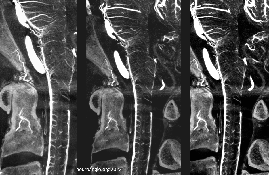
Sagittal MIPs — note striking homology between both arteries and veins of the cord and brainstem. There is nearly always present at least one prominent median brainstem vein extending to the floor of the 4th — often the collector for deep cerebellar DVAs
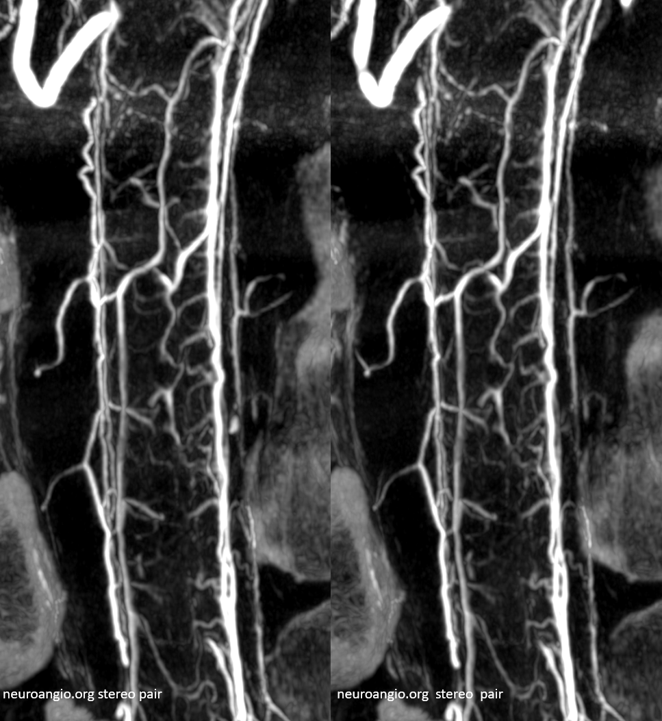
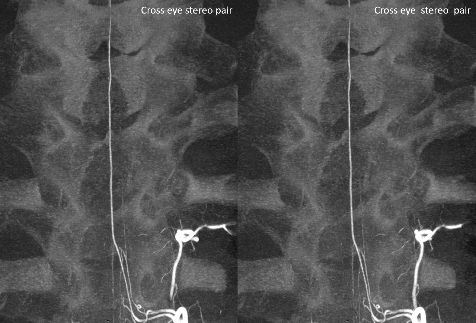
Cross eye stereo pair
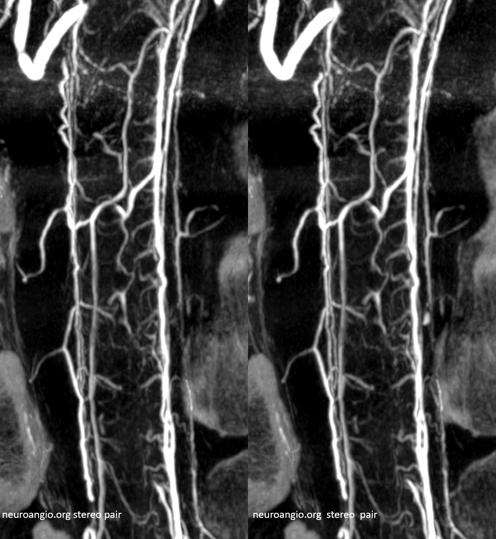
View from other side
Frontal view stereo
Cutaway stereo MIP views
Anaglyph stereos
DSA images of the same patient are below — its astounding that the above information comes from the same source — just more projections, and some state of art engineering / computer science
Paramedian Lower Medullary bilateral perforator vessels — homologs of the sulco-comissural arteries of the cord — medulla has the same basic vascular supply as cord, with larger PICA/lateral medullary supply.
Supreme Intercostal Origin Anterior Spinal Artery Cone Beam CT — Coronal views — see multiplicity of spinal radicular veins and intrinsic cord detail
Coronal MIPs
Sequential coronal MIP images
Rotational MIP
Coronal MIPs
DSA images of the same patient
Thoracic region: The artery of thoracic enlargement (Adamkiewicz) usually comes of T9 through T12 region. There is often a region of thoracic cord (mid-lower, depending on the Adamkiewitz origin, which is rather small in caliber, relative to the more well-developed cervical region vessel. A “watershed” of sorts (yellow) therefore exists which occasionally may correspond to cord infarction in states of hypotension. This double catheter injection (done for evaluation of cord infarction in the region of the basket, below the watershed) demonstrates the slender size of mid-to-lower thoracic ASA. Red=ASA; Purple=radiculomedullary arteries
The artery of Adamkiewicz. Typical appearance. Another patient, with stereo views of the radiculomedullary artery. The radiculomedullary artery (pink) often demonstrates a small segment of narrowing at the point where it pierces the dura (white arrow). The intradural segment (blue) opacifies the anterior spinal artery (red). RDC (catheter) is labeled in green.
Radiculomedullopial artery. By definition, the radiculomedullary artery is a radicular artery which supplies the ASA (red). A radiculopial artery is one which supplies the pial (posterior spinal) system (yellow). When one does both (orange), it is called radiculomedullopial. So there…
The reality is that the number of radiculomedullary and radiculopial arteries is as directly related to the actual anatomy as it is to the equipment with which it is imaged. Better machines always means more vessels. Plus the fact that life does not read books. Below is an example of a radiculomedullopial arrangement with a posterior spinal artery so large that it is essentially the reverse of what “normal” should be — much larger than the ASA. This happens rarely, but when it does, the location is cervical or mid-thoracic spine.
Regular DSA — diagnostic but not super clear
The PSA is off midline
Now comes DYNA CT — amazing difference — stereo volume-rendered images
MIP
MP4 — pause and scroll thru individual images
Flat Panel CT (DYNA CT) visualization
The difference in level of detail between DYNA and DSA is vast. Although flat panel CT is mostly used in the head, its potential to visualize spinal structures is incredible. Look at the difference below — no intrinsic cord vessels can be seen on DSA, vs clear sulco-commissural vessels on DYNA
Radiculomedullary and Radiculopial Arteries from Supreme Intercostal
Another example of DYNA Difference. Angio
DYNA MIPs — see how extensive the posterior spinal network can be — these are NOT stereos
Cross-eye stereo
Volume Rendered STEREO images
GIF
MP4– pause and scroll
Conus Imaging — Suspected Stroke — Proven Normal Arterial Supply to Conus
Occlusion of Proximal Segmental Artery
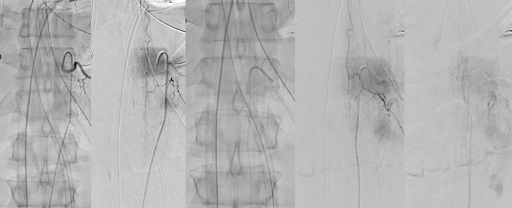
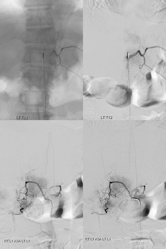
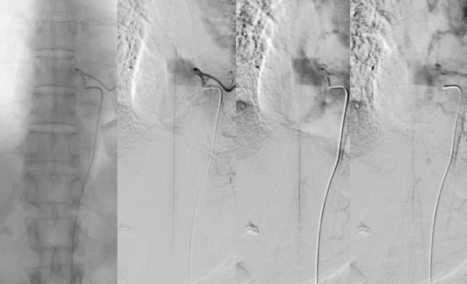
These are very common in atherosclerotic aortas, and rarely result in cord infarcts due to abundant collaterals to the segmental artery from ipsi and contralateral sources. Below is an example of left L1 segmental artery occlusion. The Adamkiewicz is supplied just fine via the right L1 through epidural arcade anastomosis. The intercostal artery and portions of the vertebral body are supplied via the left T12
Venous Phase Radiculomedullary / Spinal Artery
Venous phase of radiculomedullary artery — critically important, injection of a dominant Adamkiewicz should result in visualization of spinal veins in the venous phase. This is particularly well seen in slender patients but should be present in everyone. Failure to see these veins should be considered strong evidence of spinal venous congestion, until proven otherwise. If a dural fistula is suspected, it must be searched for until found (injecting median sacral and iliac arteries, especially, when all else is negative). More on this can be found on the Spinal Venous Anatomy page
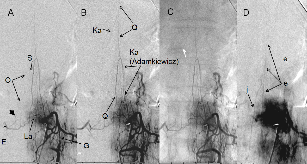
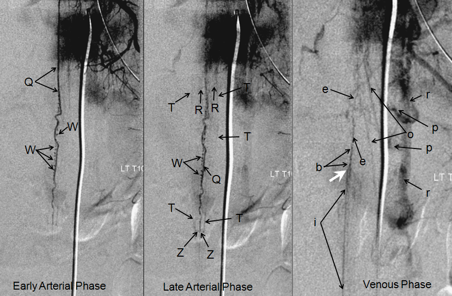
Figure 9 A-D: A – early arterial, B – late arterial, C – native, and D – venous phase images. The artery of Adamkiewicz (Ka), originating at left L1 level, opacifies the anterior spinal artery (Q). The force of contrast injection transiently reverses flow in a smaller radiculomedullary contributor (Ka) sephalad of the Adamkiewicz. A faint radiculopial artery (O) from contralateral right L1 level is visualized through the anterior epidural arcade (La). Notice subtle caliber change where the radiculopial artery pierces the dura (short black arrow). D- venous phase image demonstrating expected visualization of spinal vein (e, either anterior or posterior), and the “Great Radicular Vein” (j), the venous homolog of the Adamkiewicz.
These are some of the most gorgeous spinal images I’ve seen, courtesy of Dr. Tibor Becske. The patient presented for pre-surgical embolization of thyroid metastasis to the T8 vertebral body. Notice faint visualization of the anterior spinal artery (white) from the right T8 segmental injection. For more information on pre-procedural identification of the anterior spinal artery, see Cases 1 and 2 in Case Archives.
The main contributor to the anterior spinal axis (Adamkiewicz, ) arises from the left T11 level. The tumor can still be embolized from the right T8 level as long as the Adamkiewicz can adequately reconstitute the anterior spinal axis at the level supplied by the right T8 segment. This can be determined by Balloon Test Occlusion of the right T8 radiculomedullary artery while injecting the level of the Adamkiewicz. The decision is made on angiographic basis as the patient is asleep and, in my opinion, the exam is too unreliable in the time span of the BTO. If the patient passes BTO, the right T8 radiculomedullary artery is closed (very tightly) with coils, and the tumor can then be embolized (particles). So, below is an injection of the left T11 Adamkiewicz (pink) with balloon inflated in the right T8 ventral division (black). Notice amazing visualization of the anterior spinal axis (white), with contrast reflux into the radiculomedullary arteries at the right T8 level (light blue) and left T10 levels (dark blue). Also extremely well seen are long contiguous segments of the posterior spinal artery on the right and somewhat shorter but still quite extensive for the posterior spinal system segment on the left (purple arrows), The PSAs are opacified via the well-seen vasocorona (pial) networks (green), retrogradely visualizing radiculopial contributing vessels (orange). The left T10 level supplies both anterior and posterior spinal arteries, and therefore would be technically radiculomedullopial.
This kind of anatomy is best seen in stereo:
Variant high origin of thoracic ASA. The “Adamkiewicz” can occasionally (25% of the time) come off unusually high or low. In these cases, there is often variation in terms of posterior cerebral artery anatomy as well. In this patient, a large Left T5 level radiculomedullary artery supplies the ASA (white) of entire thoracic spine. Patients like these are at a somewhat higher risk of cord infarction, having little in the way of collateral radiculomedullary ASA supply. An unusually prominent posterior spinal artery (red) is present also.
Where can ASA be hiding?
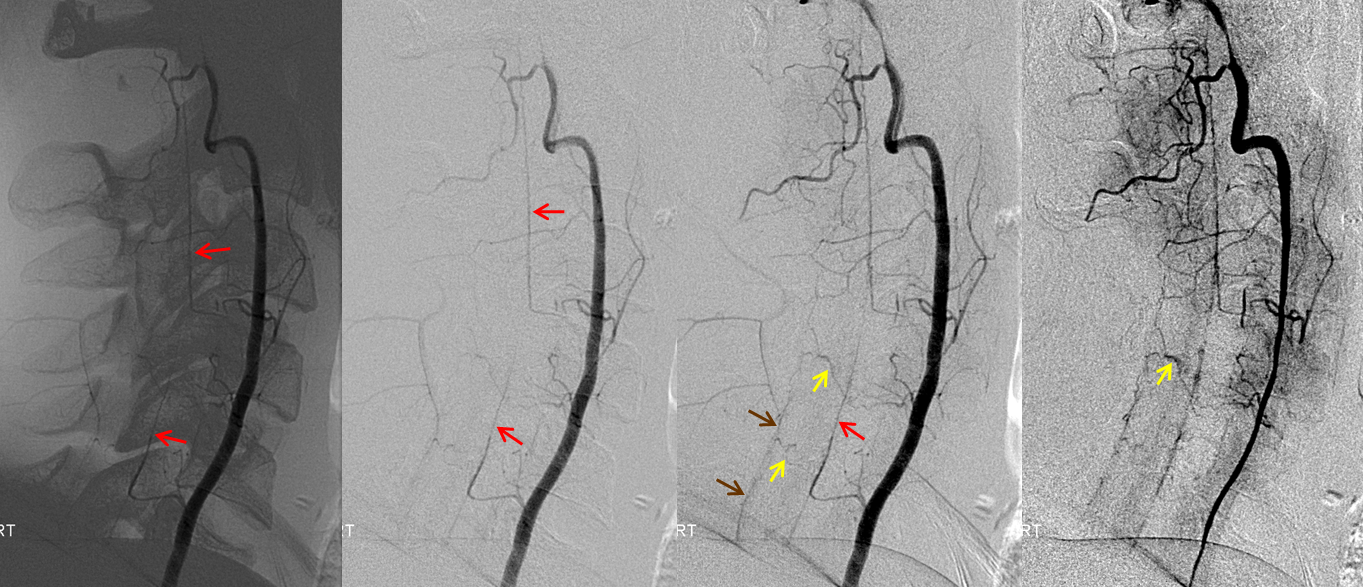
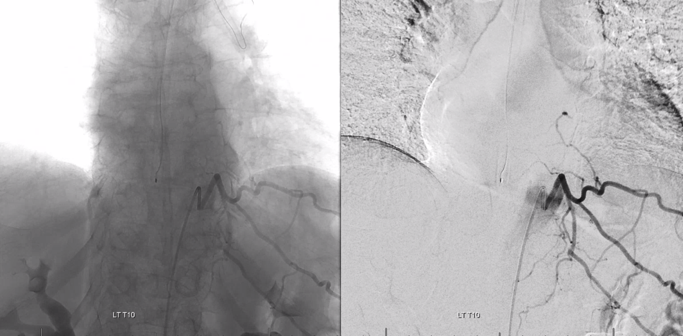
It is important to understand that in a neurologically normal patient the ASA has to be there, somewhere. if you are not finding it, look harder. Here is a nice illustration of “common origin” right T9, T10, and T11 intercostal arteries from the right T10 segmental artery
However, understanding of anatomy lead leads one to know that neither T9 nor T11 segmental arteries are completely missing. The anastomosis (G, black arrows below) is distal to origin of the radicular / radiculomedullary region branch (E). A small segmental artery is present, with its supply limited to the anterolateral vertebral body (gray arrows)
Indeed, after some effort exactly this kind of hypoplastic right T9 segmental artery is identified, supplying the vertebral body and giving rise to the radiculomedullary artery
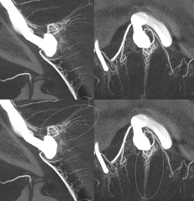
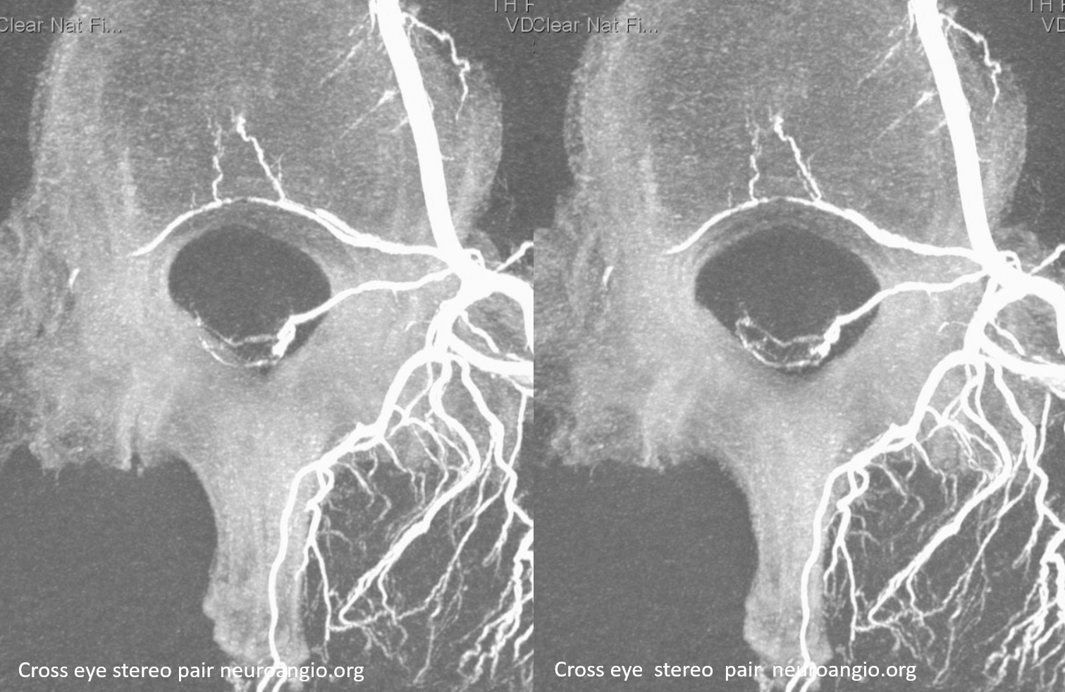
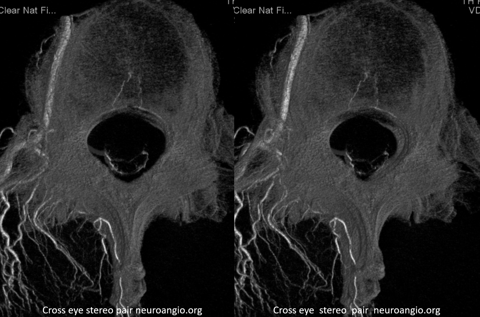
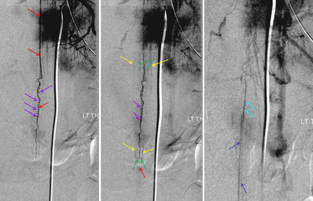
Conus region — the terminal region of the cord, conus medullaris, is quite vascular. It is usually visualized as an arterial “basket”, consisting of the anterior spinal artery and two “posterior” spinal arteries, which which are anastomosed at the bottom of the conus via the rami cruciantes (blue, “Z” in figure 2). Multiple radicular arteries, supplying the nerve roots of the cauda equina, are usually opacified through the basket (unlike the rest of the cord, where radicular arteries are usually visualized via segmental arterial injections, and normally flow towards, rather than away from the cord). Because of its rich vascular supply, later phase images usually allow for visualization of spinal veins. This can be important, if an agiogram is being perfromed to locate an occult spinal dural fistula. Usually, the fistula drains into spinal veins, and presents as venous congestion of the cord. Therefore, injection of spinal arteries in these patients usually does not visualize normal veins, as these are being congested by the fistula. Therefore, seeing morphologically normal veins at appropriate venous phase time (3-5 seconds following arterial phase) is good evidence that either 1) no fistula is present, or 2) it does not congest spinal veins.
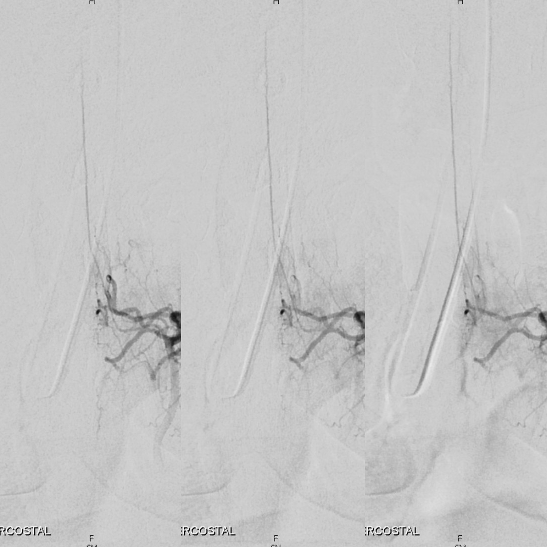
In this young patient, the conus region “arterial basket” is particularly well displayed. The anterior spinal artery (red) opacifies, via coronary arteries at the bottom of the conus (dark and light blue arrows) the lateral spinal (posterior spinal) systems (yellow arrows). Notice, in an image to the left, how a more superior segment of the anterior spinal artery (white) is visualized through the retrocorporal arcade (pink arrow).
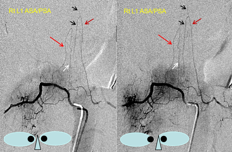
Arterial “basket” consisting of the anterior spinal artery (black) and lateral/posterior spinal arteries (white) can often be visualized from an appropriate radiculomedullary artery injection (purple for radiculomedullary and red for radiculopial). In this case, the posterior spinal network is coming from left L1, and radiculomedullary artery (purple) to the ASA from the right L1, but both can be seen secondary to cross-filling.
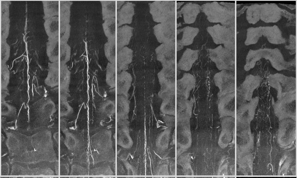
Another example of prominent posterior spinal network at the conus — this is important — these vessels can be very large, and dominate supply of conus region. Their occlusion is likely to produce serious conus symptoms and be in differential of other conus problems. Here is an example with amazing DYNA images
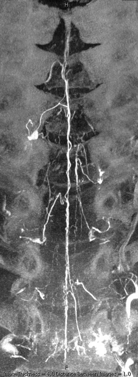
Standard DSA shows large Adamkiewicz from left T9, however it does not go to conus. Venous phase image on right shows good filling of veins.
The conus is supplied by a large posterior spinal from left L1 (the origins of posterior spinals from thoracolumbar junction area are much more consistent than origin of Adamkiewicz). The transverse “corona” vessels on the posterior cord connect to the large right posterior spinal as well. Image on right shows well the venous system — testament to large area of supply by the posterior spinal system
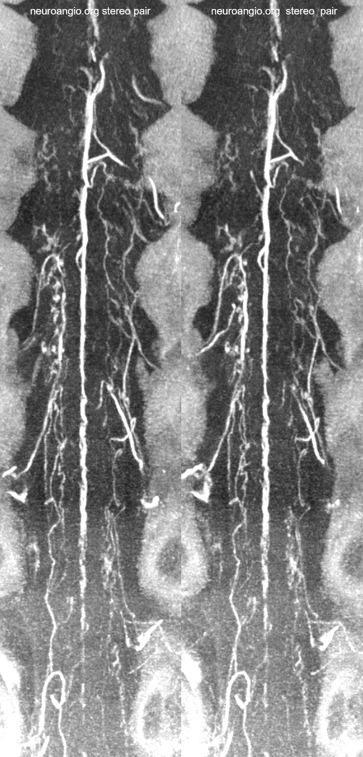
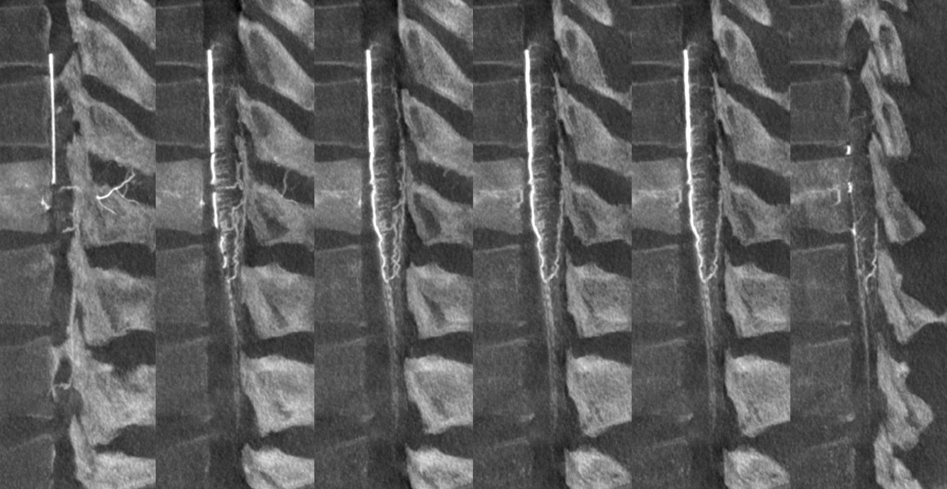
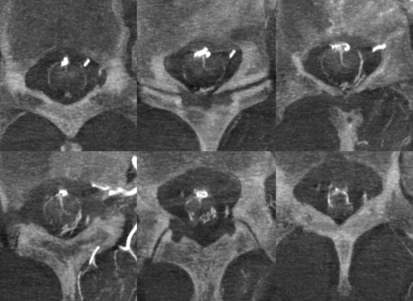
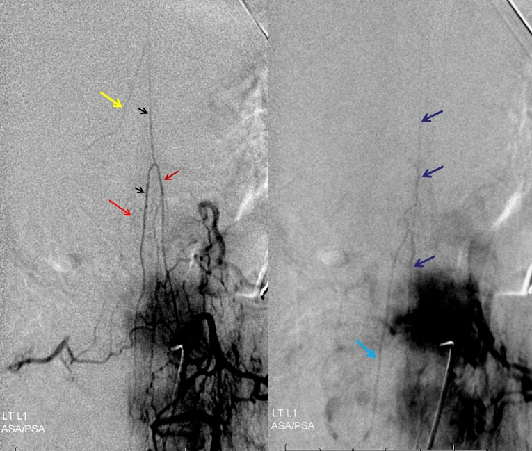
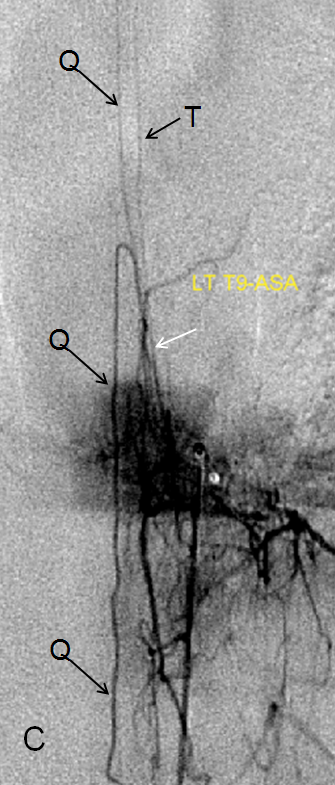
Normally, intrinsic arteries of the spinal cord are angiographically invisible, even under optimal conditions of general anesthesia and paralysis (which is how we do spinal angiography). In this young, very thin patient, injection of the Adamkiewicz beautifully visualized multiple end-on sulco-comissural vessels, seen as dots (purple, W) next the anterior spinal artery (red, Q). Notice multiple coronal surface vessels (green, V) which opacify the posterior spinal channels (yellow, T), which are usually contiguous at the conus (rami cruciantes, or Z, labeled in green at the bottom). Venous phase image (right) shows a slanting direction radicular vein (dark blue), as is often the case, draining the basket. A hint of radiculomedullary veins is present also (light blue)
Venous phase component of Anterior spinal artery injection — more fully treated in the Spinal Venous Anatomy page. It is crucial to note that injection of a dominant ASA should lead, under appropriate conditions of general anesthesia and paralysis, to visualization of the spinal veins, 4-8 seconds later. What is typically seen is a single spinal vein running in parallel with the anterior spinal artery, and one or several radicular veins. There is often a “great radicular vein” present, like the “great radiculomedullary artery of Adamkiewicz) but almost never at the same level as the Adamkiewicz. It is critically important to see spinal veins in cases where dural fistula is being suspected, because fistulas typically congest these veins to such an extent that they are not visualized on ASA injections. In other words, if you inject the ASA but dont see spinal veins, it is likely that the reason is spinal venous congestion.
Below, venous phase images of the same injection demonstrate an anterior spinal vein (dark blue) and radiculomedullary vein (light blue).
POSTERIOR SPINAL NETWORK The posterior spinal arteries, classically shown as two small paired vessels running along the back surface of the cord, do not exist as such in reality. They are in fact a discontinuous longitudinal system supplied via radiculopial (as opposed to radiculomedullary) vessels which run along the pial surface of the cord dorsally to supply a posterior spinal artery segment which usually spans no more than several levels. The situation is occasionally different and the PSA can be quite long (see case below). It can be recognized then as a relatively straight vessel located OFF MIDLINE with respect to the spinous processes (the ASA must be midline unless there is significant unilateral mass effect present, which is usually known beforehand from cross-sectional imaging). Exceptions to posterior spinal discontinuity are found at both ends of the cord — the “basket” at the bottom, already discussed above, whereby the posterior spinal vessels are seen through the “rami cruciantes” and in the cervical spine, where it takes form of the somewhat controversial “lateral spinal artery”
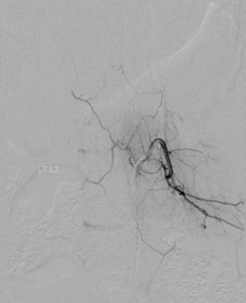
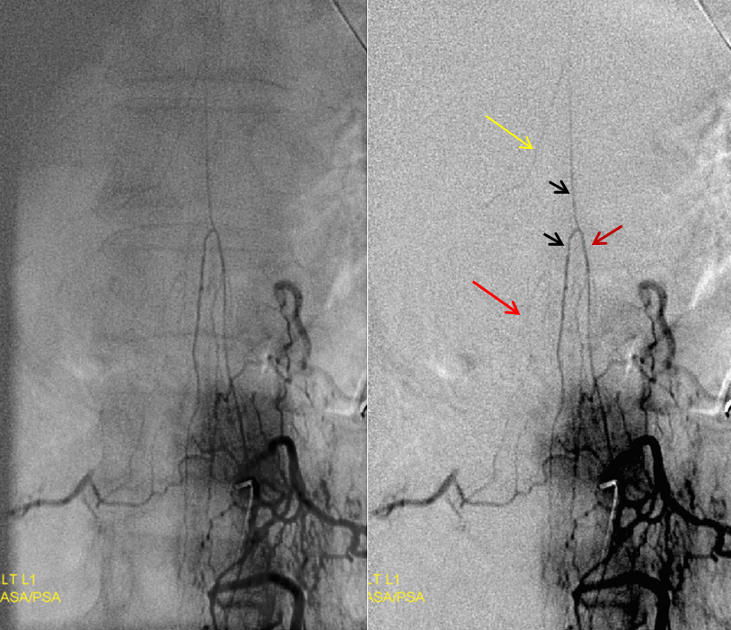
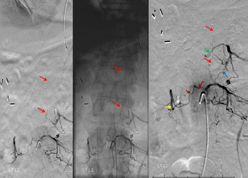
Posterior spinal artery (red) visualization from the Left L2 segment. The artery is off midline as seen on the middle native AP image. Notice also opacification of the contralateral Right L2 level (yellow) via the retrocorporeal arcade (Brown) opacifying the ventral division (white); the paravertebral anastomotic network (blue) opacifies the ipsilateral left L1 level segmental vesses (green).
Unusually promient PSA (red arrows, off midline) in association with high origin and poor collateral support of the artery of thoracic enlargement (white). Same case as above in the ASA section.
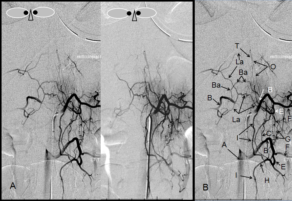
Another demonstration of posterior spinal arterial anatomy.
A — Stereo pair, and B – legend, demonstrating multiple transverse and longitudinal anastomotic connections. The pre-vertebral anastomosis, hallmarked by its proximal location relative to segmental artery ostium, is labeled “C”. Also present are pre-transverse (G) and post-transverse (I) anastomoses. A not so commonly encountered anastomosis between two proximal segmental arteries (Ba) is present, along the anterior circumference of the vertebral body. A prominent posterior spinal artery (T) and its radiculopial feeder (O) can be seen, in an off-midline position.
Radiculomedullopial artery — when both anterior (Q) and posterior (T) spinal arteries are supplied by one common radicular vessel, that’s the name.
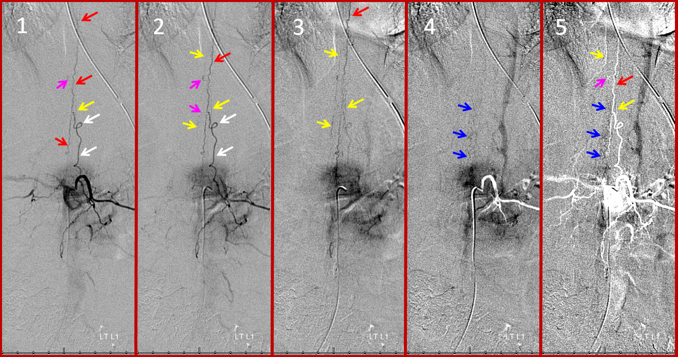
Pial Arterial (Vasocorona) network — the cord is covered by multiple surface mesh-like arteries which connnect the anterior and posterior spinal systems. They are almost never seen due to their small size, except in cases when a particularly large one happens to be present (usually when the posterior spinal artery happens to be supplied via this kind of vessel from the anterior spinal artery). This is one such case:
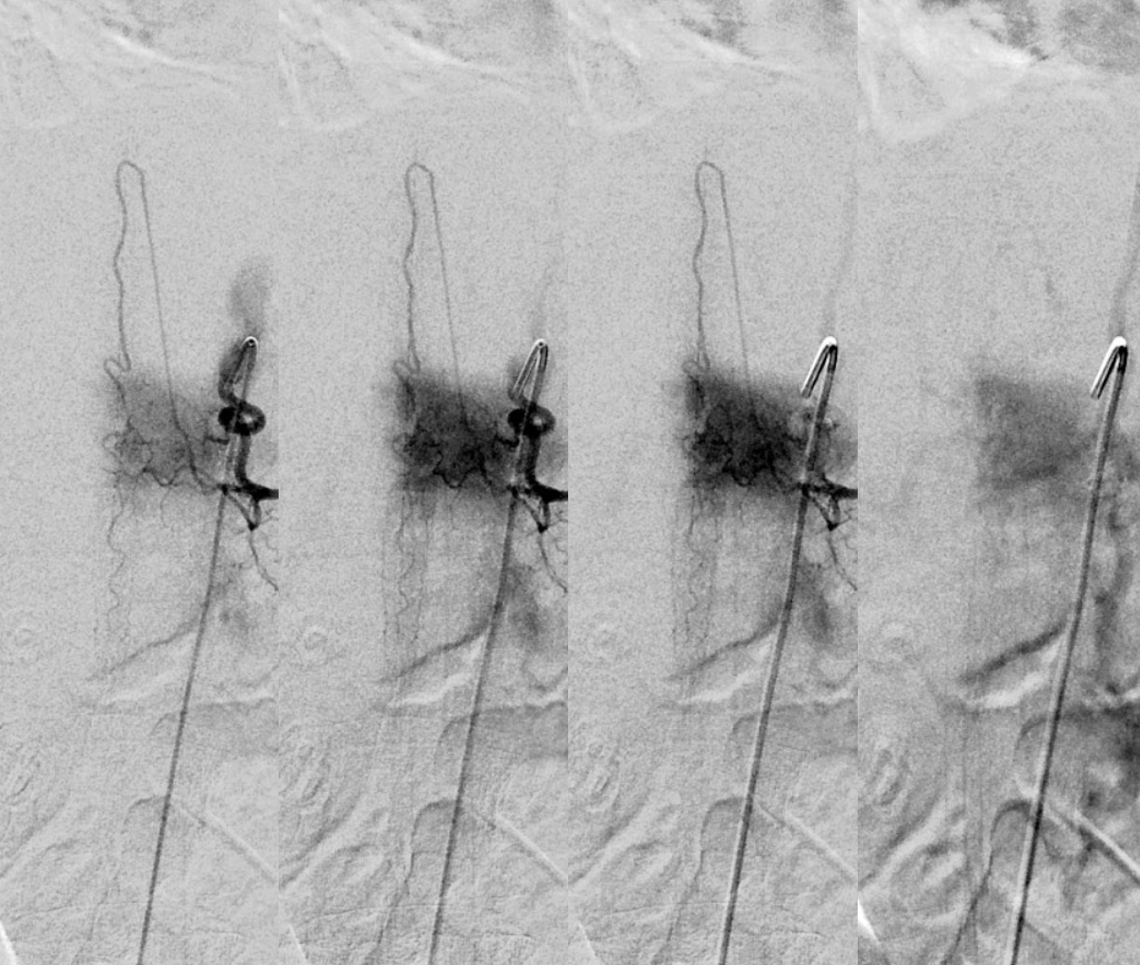
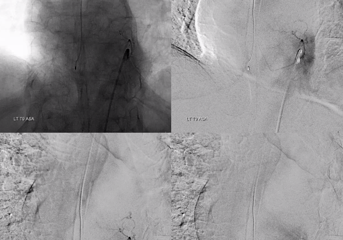
Images 1-5 in time sequence, from earliest to latest. In this thin patient, the radiculomedullary artery (white) supplies the anterior spinal artery (red). Both left and right posterior spinal arteries (yellow arrows) are visualized via two “vasocorona” or pial arteries (pink, letter “V” in the diagram on top of page). These arteries run on the surface of the cord. Venous phase images visualize the perimedullary spinal venous network (blue arrows, images 4 and 5). Image 5 is the same timepoint as 4, with the mask image adjusted to show the arterial phase in white. Once Again: Injection of a dominant (Adamkiewitz, in this case) radiculomedullary artery should allow, with use of modern equipment and appropriate technique (meaning general anesthesia, full paralysis, apnea during image acquisition, and glucagon-induced bowel paralysis, if necessary) visualization of the spinal veins at the appropriate time point (perhaps around 5 seconds artery to vein circulation, with variability depending on conditions). Failure to visualize spinal veins under these conditions, particularly when looking for a spinal fistula, should be taken as indirect evidence of existence of such fistula elsewhere, with secondary venous congestion.
Visualizaton of the pial network of the thoracolumbar cord is limited by the body habitus of the patient, which works against resolving small vessels even under conditions of perfect paralysis and apnea. The situation is much better in the cervical spine, where pial vessels (yellow arrows) bridging the anterior spinal (red) and posterior spinal (brown) axes can be seen, as below. Notice the discontinuous nature of the posterior spinal network, in contrast to the straight anterior spinal artery.
Lateral Spinal Artery — see also Vertebral Artery and PICA pages. Lateral spinal artery is a fascinating vessel — it is an artery present on the lateral aspect of the upper cervical cord and cervicomedullary junction. Lasjaunias and others consider the PICA to be a hypertrophied lateral spinal artery, recruited to supply cerebellar territory. This powerful concept explains many PICA variations — for example the C1 or C2 origin PICA is essentially a larger lateral spinal trunk ultimately connected to the intracranial PICA. This is also important in understanding the “lateral medullary syndrome” of Wallenberg and its variants — the infarct basically corresponds to the territory of the lateral spinal artery.
In this patient, the right vertebral artery is occluded just below the foramen magnum due to dissection. The C1 radiculopial artery (purple) connection to the lateral spinal artery (red) allows for reconstitution of the vermian branch of the PICA (black). The lateral spinal artery below the C1 radiculopial branch is marked with the pink arrow. Notice also presence of the anterior spinal artery (yellow) perfectly contrasting its anterior and medial position to that of the spinal artery. The C1 radicular branch (purple) is in effect the radiculopial artery is acting as a radiculopial artery, homologous to radiculopial supply of the posterior spinal arteries at the thoracic and lumbar levels. The C1 muscular branch (green) opacifies the occipital artery (white) and deep cervical artery (blue).
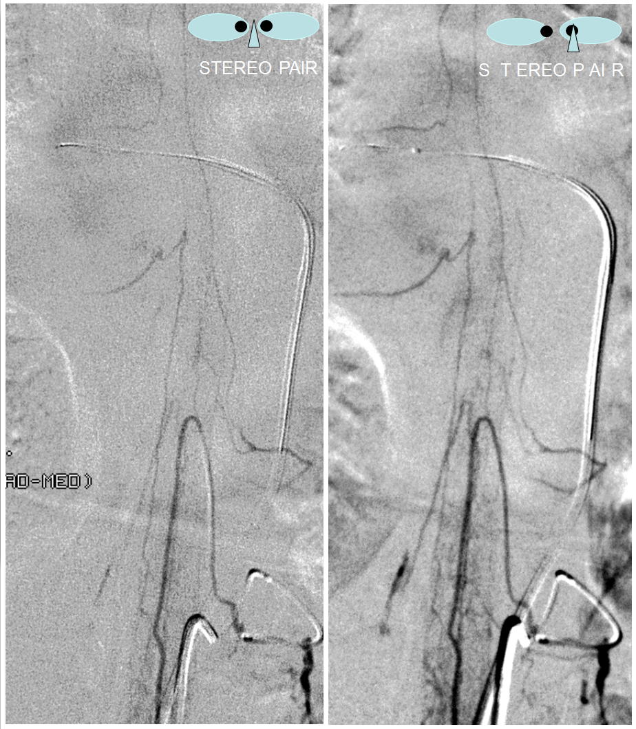
The indispensable STEREO pair
Sulco-commissural arteries (W)
These vessels (W), typically arising from the anterior spinal artery, penetrate into the ventral median sulcus to reach the center of the cord, from where numerous centrifugal intrinsic arteries (Y) emerge to predominantly supply the gray matter of the cord. This represents the main intrinsic cord supply system. On the surface of the cord, rami perforantes (X) penetrate to a variable but short extent into the substance of hte cord. They seem to be more prominent in relation to the posterior spinal system, as the centrifugal system does not typically supply the dorsal columns. The sulco-commissural vessels (W), as all intrinsic cord vessels, are usually below the resolution of in-vivo spinal angiography; occasionally, a good injection of a dominant Adamkiewicz, in a particularly slim patient, is successful in visualizing these arteries end-on as dots, thus defining the location of the ventral median sulcus, as in the case below.